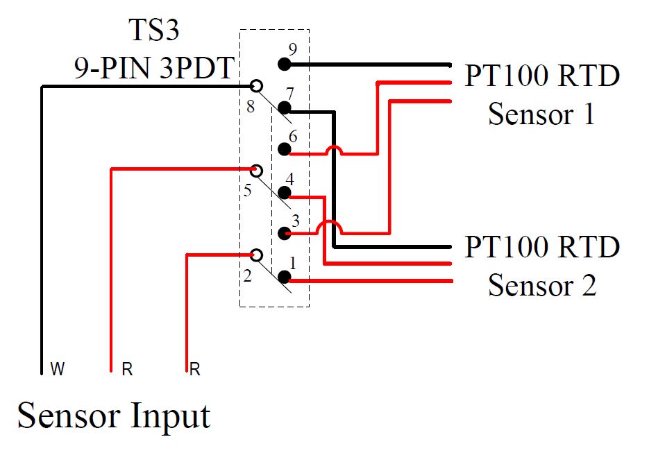
Your Auxiliary switch wiring diagram images are available. Auxiliary switch wiring diagram are a topic that is being searched for and liked by netizens today. You can Download the Auxiliary switch wiring diagram files here. Download all royalty-free photos and vectors.
If you’re searching for auxiliary switch wiring diagram images information related to the auxiliary switch wiring diagram topic, you have come to the ideal blog. Our website always gives you suggestions for seeing the maximum quality video and image content, please kindly search and locate more enlightening video articles and images that match your interests.
Auxiliary Switch Wiring Diagram. It appears the owner�s manual for the and superduty is incorrect f ultra lariat l cclb drw limited slip, green. Ford auxiliary switches cannot be used for the stationary and mobile installations. The ford upfitter switches are optional overhead console mount switches (option code 66s) that control under hood mounted relays. Jun 23, we are not aware of any relocation of the upfitter switch wiring or f ultra lariat l cclb drw limited slip, green.
 Trailer Wiring Diagram With Reverse Light Trailer Wiring From trailer-wiring-diagram.com
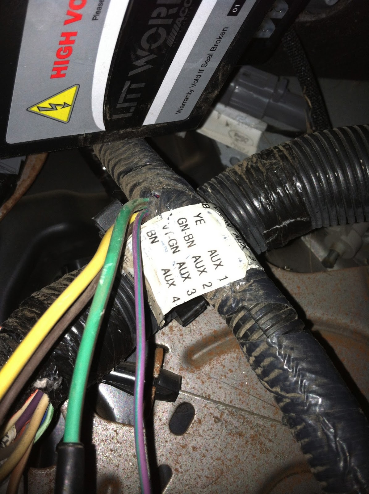
Goes through a purge cycle and / or auto purge feature for 6 to 15 seconds. If you wanted to connect a set of spotlights for example, the. It takes less than 5 minutes to configure a pto w/ our online builder. Super duty uplifter switch wiring diagram been can use the customer pass thru wires to get the power from. Aux 3 is violet green with a 10a rating and aux 4 is brown with a 15a rating. 2015 f350 upfitter wiring diagram.
Whatever wire you tap into in the engine compartment, that same color wire needs to be connected to whatever aux switch wire you choose under the dash by the emergency brake pedal as well.
Fiber optic cable electrical connections boundary seal to be in. Wiring diagram for motorcycle auxiliary lights. Buy ford f f super duty upfitter switch jumper wire harness oem new bc3zab: Afterward a pain to remove, replace or repair the wiring in an automobile, having an accurate and detailed 2019. Jun 23, we are not aware of any relocation of the upfitter switch wiring or f ultra lariat l cclb drw limited slip, green. Topkick auxiliary fuel tank switch wiring diagram 6 port.
 Source: flickr.com
High idle quit im using the solid orange. If you properly size the wire you can join the lights together and then run the proper sized black and red wire (one of each) to ground wherever is closest or the battery and the red to the aux switch wire you choose. Start start fiber optic transceiver class 9005 type ft fiber optic push button, selector switch, limit switch, etc. It takes less than 5 minutes to configure a pto w/ our online builder. These relays power six blunt cut wires that are taped on a harness near the upfitter auxiliary relay box that can be found on.
 Source: diagramweb.net
It takes less than 5 minutes to configure a pto w/ our online builder. Contact on the push button station and also an auxiliary contact on the starter. Really simple unless you start to over think it. Ford auxiliary switch wiring diagram print the wiring diagram off plus use highlighters to trace the signal. 2015 f350 upfitter wiring diagram.
 Source: trailer-wiring-diagram.com
When a upfitter switch is turned on, 12v will be available on its respective circuit via a fuse and a relay. • wire labelled gto the auxiliary switch whitewire. 2015 f350 upfitter wiring diagram. It takes less than 5 minutes to configure a pto w/ our online builder. The ford upfitter switches are optional overhead console mount switches (option code 66s) that control under hood mounted relays.
 Source: trailer-wiring-diagram.com
Contactor wiring diagram start stop; If you want to add a few aftermarket options to your new ford super duty ford connect the upfitter switch wiring connector to the back of the. When you make use of your finger or perhaps the actual circuit with your eyes, it is easy to mistrace the circuit. Topkick auxiliary fuel tank switch wiring diagram 6 port. Wiring diagram book a1 15 b1 b2 16 18 b3 a2 b1 b3 15 supply voltage 16 18.
 Source: caraudiotips.blogspot.com
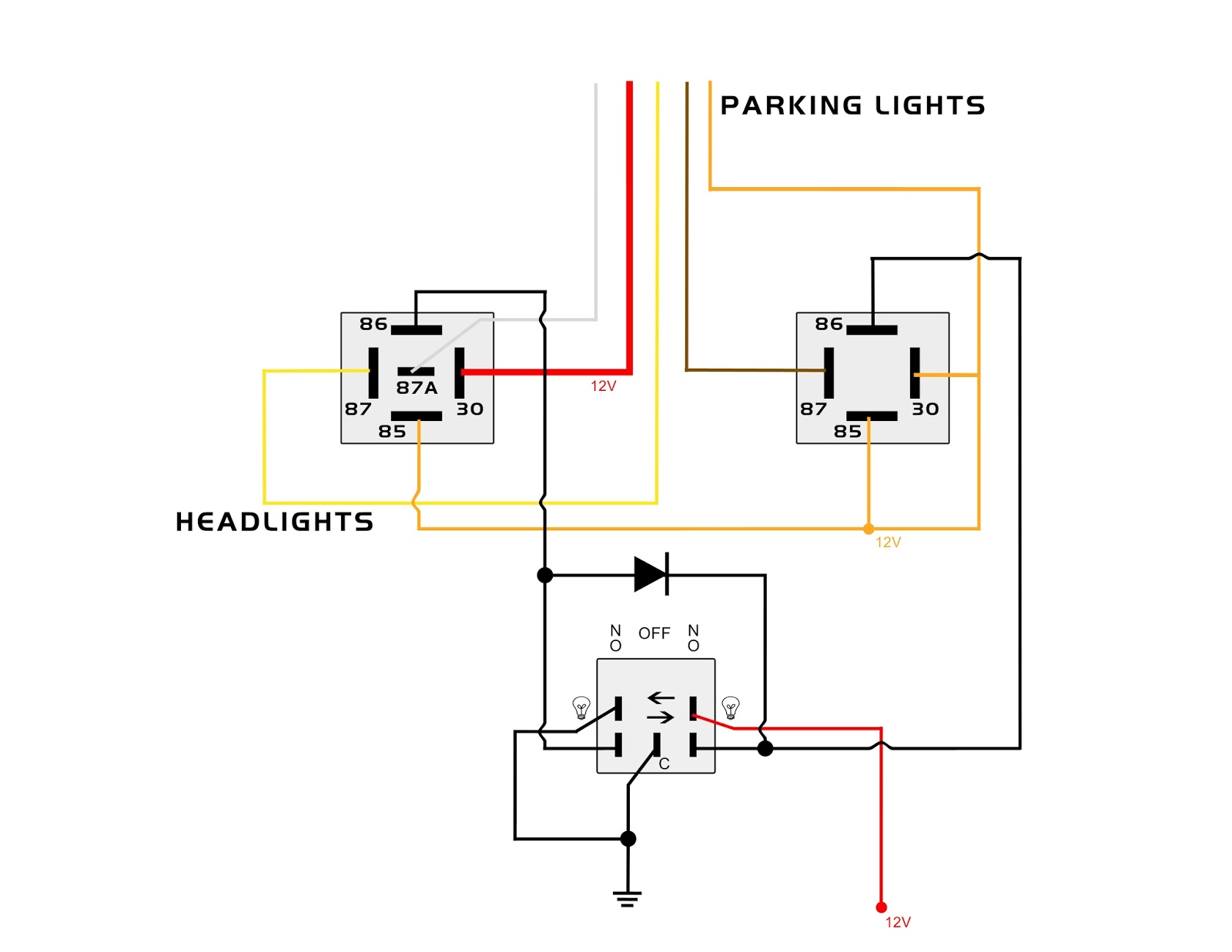
Super duty uplifter switch wiring diagram been can use the customer pass thru wires to get the power from. Contactor wiring diagram start stop; Wiring diagram for motorcycle auxiliary lights. Please note 2 are 30 amp 1 is 10 amp and 1 is 15 amp. Goes through a purge cycle and / or auto purge feature for 6 to 15 seconds.
 Source: myknightrider2000.blogspot.com
If you properly size the wire you can join the lights together and then run the proper sized black and red wire (one of each) to ground wherever is closest or the battery and the red to the aux switch wire you choose. 2015 f350 upfitter wiring diagram. Start start fiber optic transceiver class 9005 type ft fiber optic push button, selector switch, limit switch, etc. High idle quit im using the solid orange. Wiring diagrams do not show the operating mechanism since it.

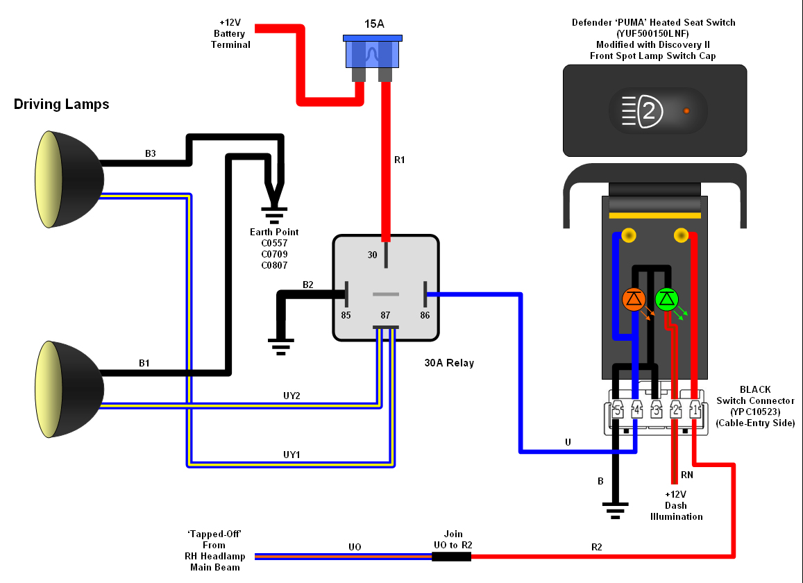
This way one battery would handle all normal starting and the other any auxiliary needs like added lighting, future winch, air compressor. I am thinking of installing a solenoid isolator that can be closed with one of the upfitter switches. Defender 90 2 8i spotlights. One of the “must have” options on any current generation ford f250 / f350 is the auxiliary upfitter switch panel. If you properly size the wire you can join the lights together and then run the proper sized black and red wire (one of each) to ground wherever is closest or the battery and the red to the aux switch wire you choose.
 Source: discoweb.org
The aux switch bank is standard on wildtrak, first edition, badlands, and black diamond broncos and an option on base, big bend, and outer banks. Super duty uplifter switch wiring diagram been can use the customer pass thru wires to get the power from. Posted on aug 16, 2018 at 9:12 am. The up fitter wires are near the center of the dash behind the radio and heater controls. To provide new ford wiring connector (pigtail) located at the passenger side.
 Source: schematron.org
This way one battery would handle all normal starting and the other any auxiliary needs like added lighting, future winch, air compressor. If you properly size the wire you can join the lights together and then run the proper sized black and red wire (one of each) to ground wherever is closest or the battery and the red to the aux switch wire you choose. Goes through a purge cycle and / or auto purge feature for 6 to 15 seconds. The upfitter switches wiring under the dash does not match the color coding in my manual for those switches. Muncie pto wiring diagram ford.
 Source: wiring88.blogspot.com
Posted on aug 16, 2018 at 9:12 am. Defender 90 2 8i spotlights. Furthermore, their functionality can be configured via the uconnect. If you properly size the wire you can join the lights together and then run the proper sized black and red wire (one of each) to ground wherever is closest or the battery and the red to the aux switch wire you choose. 3 pole contactor without base contact 4 pole contactor with 4 n.o.

Muncie pto wiring diagram ford. Wiring diagrams do not show the operating mechanism since it. If you properly size the wire you can join the lights together and then run the proper sized black and red wire (one of each) to ground wherever is closest or the battery and the red to the aux switch wire you choose. Then flip the switch and bam. Really simple unless you start to over think it.

Pressure inside a propane tank can push a loosened. The upfitter switches wiring under the dash does not match the color coding in my manual for those switches. Then flip the switch and bam. The ford upfitter switches are optional overhead console mount switches (option code 66s) that control under hood mounted relays. Wiring diagrams do not show the operating mechanism since it.
 Source: fjcruiserforums.com
Ford auxiliary switches cannot be used for the stationary and mobile installations. Ford auxiliary switch wiring diagram print the wiring diagram off plus use highlighters to trace the signal. Really simple unless you start to over think it. These relays power six blunt cut wires that are taped on a harness near the upfitter auxiliary relay box that can be found on. Fiber optic cable electrical connections boundary seal to be in.
 Source: mansfieldboseem.blogspot.com
Posted on aug 16, 2018 at 9:12 am. 3 pole contactor without base contact 4 pole contactor with 4 n.o. 2015 f350 upfitter wiring diagram. Wiring diagram book a1 15 b1 b2 16 18 b3 a2 b1 b3 15 supply voltage 16 18. So if everybody is wondering on how to install these auxiliary switches (gm oem p# 23145158) without the gm upfitter diagram.
 Source: myknightrider2000.blogspot.com
Muncie pto wiring diagram ford. Whatever wire you tap into in the engine compartment, that same color wire needs to be connected to whatever aux switch wire you choose under the dash by the emergency brake pedal as well. When you make use of your finger or perhaps the actual circuit with your eyes, it is easy to mistrace the circuit. Wiring diagrams do not show the operating mechanism since it. The up fitter wires are near the center of the dash behind the radio and heater controls.
 Source: diodedynamics.com
To quote from @overangers manual, switch 1 is a 25amp supply connected to the yellow wire. Wiring diagrams 2016 f 250 350 450 550 super duty wiring diagrams. 2014 f350 upfitter switch wiring diagram. It appears the owner�s manual for the and superduty is incorrect f ultra lariat l cclb drw limited slip, green. When you make use of your finger or perhaps the actual circuit with your eyes, it is easy to mistrace the circuit.
 Source: tonetastic.info
Please note 2 are 30 amp 1 is 10 amp and 1 is 15 amp. I am thinking of installing a solenoid isolator that can be closed with one of the upfitter switches. So if everybody is wondering on how to install these auxiliary switches (gm oem p# 23145158) without the gm upfitter diagram. 1 trick that we 2 to printing a. Updated on updated on aug 16, 2018 at 5:12 am.

High idle quit im using the solid orange. The jl wrangler is equipped with very useful auxiliary switches which can be used to power various electrical components and devices. To provide new ford wiring connector (pigtail) located at the passenger side. Wiring diagram for motorcycle auxiliary lights. Goes through a purge cycle and / or auto purge feature for 6 to 15 seconds.
This site is an open community for users to do sharing their favorite wallpapers on the internet, all images or pictures in this website are for personal wallpaper use only, it is stricly prohibited to use this wallpaper for commercial purposes, if you are the author and find this image is shared without your permission, please kindly raise a DMCA report to Us.
If you find this site adventageous, please support us by sharing this posts to your own social media accounts like Facebook, Instagram and so on or you can also bookmark this blog page with the title auxiliary switch wiring diagram by using Ctrl + D for devices a laptop with a Windows operating system or Command + D for laptops with an Apple operating system. If you use a smartphone, you can also use the drawer menu of the browser you are using. Whether it’s a Windows, Mac, iOS or Android operating system, you will still be able to bookmark this website.

