Your Autometer wideband wiring diagram images are ready in this website. Autometer wideband wiring diagram are a topic that is being searched for and liked by netizens now. You can Get the Autometer wideband wiring diagram files here. Download all free vectors.
If you’re searching for autometer wideband wiring diagram pictures information connected with to the autometer wideband wiring diagram keyword, you have come to the right blog. Our site frequently provides you with hints for seeing the maximum quality video and picture content, please kindly search and find more enlightening video articles and images that fit your interests.
Autometer Wideband Wiring Diagram. Once the civic steering column cover has been removed, you can access the ignition plug harness. Bare 1/4 of the end of the wire supplied at the sender unit. Data logging output is included for one wire or two wire systems in both lambda or afr. S this connects to the sending unit in.
 Your Price From sfxperformance.com
Once the civic steering column cover has been removed, you can access the ignition plug harness. Otherwise, the arrangement will not work as it should be. Snapper yard cruiser belt diagram; Data logging output is included for one wire or two wire systems in both lambda or afr. Wiring diagram arrives with several easy to follow wiring diagram guidelines. Hi steve, thank you for connecting with us.
Hi steve, thank you for connecting with us.
Evinrude trolling motor wiring diagram; Pin on gauges car and truck parts a wiring diagram is a streamlined standard pictorial representation of an electrical circuit. S this connects to the sending unit in. Install an eyelet terminal supplied with the kit on the end of the wire and crimp it tightly with a pair.autometer egt wiring diagram | wiring libraryautometer oil. Electric speedometer signal that can be calibrated within the. A wiring diagram is a simplified traditional pictorial depiction of an electrical circuit.
 Source: allfordmustangs.com
Data logging output is included for one wire or two wire systems in both lambda or afr. Hi steve, thank you for connecting with us. Pin on gauges car and truck parts a wiring diagram is a streamlined standard pictorial representation of an electrical circuit. Evinrude trolling motor wiring diagram; The electrical cable that is admired by the whole world.
 Source: sfxperformance.com
The blue/black is the ground wire and needs to go to pin 5 on the interface (see illustration 3). While pure gasoline has a stoichiometric ratio of 14.7:1, 10% ethanol with be 14.04:1. Autometer gauge wiring diagram you ll need a comprehensive professional and easy to know wiring diagram. Each part ought to be placed and linked to different parts in specific way. You can just use your radio harness for power/ground aem wideband wiring diagram.
 Source: schematron.org
Autometer gauge wiring diagram you ll need a comprehensive professional and easy to know wiring diagram. Evinrude trolling motor wiring diagram; From our experience, many methods cause poor wideband sensor performance due to electrical interference or insufficient grounds.the following method for wiring in a wideband oxygen sensor to a vehicle equipped with an obd1 ecu is our recommendataion for But i didn�t dig too deeply. For chrysler blue gold and silver.
 Source: schematron.org
Once you have selected a mounting location, you can run the four wires that. Each component ought to be set and linked to different parts in particular way. There are many different ways to wire in a wideband oxygen sensor. Has i think all autometer wiring diagrams, maybe more too. Each component should be placed and connected with other parts in particular manner.
 Source: iamc.com
Our specially designed o2 sensor and wiring harness are included for ease of installation. Each part ought to be placed and linked to different parts in specific way. While pure gasoline has a stoichiometric ratio of 14.7:1, 10% ethanol with be 14.04:1. Data logging output is included for one wire or two wire systems in both lambda or afr. Once you have selected a mounting location, you can run the four wires that.
 Source: speedwaymotors.com
Autometer sport comp tach wiring. It’s intended to aid all the average person in developing a suitable method. Bare 1/4 of the end of the wire supplied at the sender unit. It includes diagrams for common ignition systems, including those used by general motors, ford, and chrysler plus many aftermarket manufacturers. Sorry if it has been posted prior.

Auto meter sport comp tach wiring. The wiring diagram shown is a typical installation. If not, the structure won’t work as it ought to be. Our specially designed o2 sensor and wiring harness are included for ease of installation. Autometer has designed their tach to be used with four six.

Generac guardian 45kw engine wiring diagram; The wiring diagram shown is a typical installation. It includes diagrams for common ignition systems, including those used by general motors, ford, and chrysler plus many aftermarket manufacturers. Generac guardian 45kw engine wiring diagram; Evinrude trolling motor wiring diagram;
 Source: americanmuscle.com
These guidelines will be easy to understand and apply. Wiring connect the tachometer wires as shown. From our experience, many methods cause poor wideband sensor performance due to electrical interference or insufficient grounds.the following method for wiring in a wideband oxygen sensor to a vehicle equipped with an obd1 ecu is our recommendataion for Autometer sport comp tach wiring. The wiring diagram shown is a typical installation.
 Source: gautoparts.com
Gauge can be mounted in a 21⁄ 16” dia. Wiring diagram arrives with several easy to follow wiring diagram guidelines. Auto meter sport comp tach wiring. From our experience, many methods cause poor wideband sensor performance due to electrical interference or insufficient grounds.the following method for wiring in a wideband oxygen sensor to a vehicle equipped with an obd1 ecu is our recommendataion for S this connects to the sending unit in.

Gauge can be mounted in a 21⁄ 16” dia. Electric speedometer signal that can be calibrated within the. Wiring diagram arrives with several easy to follow wiring diagram guidelines. A wiring diagram is a simplified traditional pictorial depiction of an electrical circuit. Ok for use with nitrous oxide.
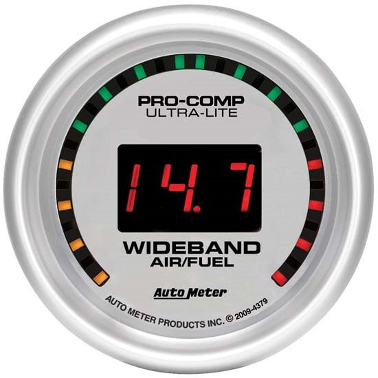 Source: speedwaymotors.com
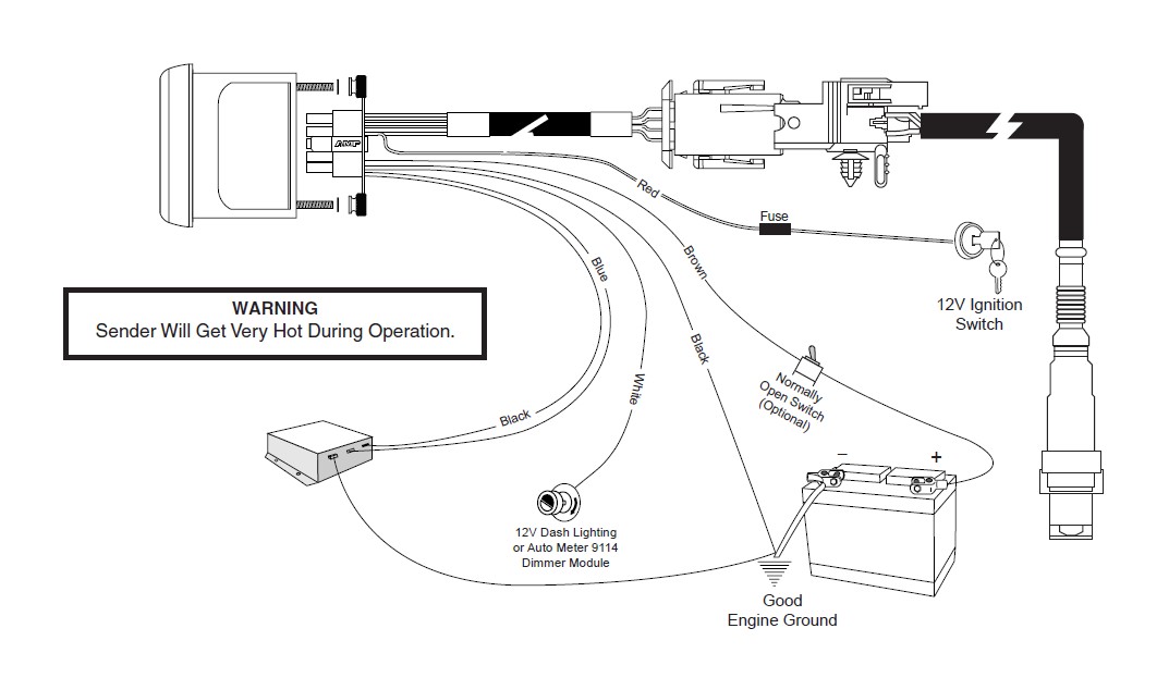
Autometer gps speedometer wiring diagram auto meter diesel tach wiring diagram wire center u2022 rh. 12 volt lifepo4 rv wiring diagram Each component should be placed and connected with other parts in particular manner. Each part ought to be placed and linked to different parts in specific way. There are two output wires from the autometer wide band (blue and a blue / black).
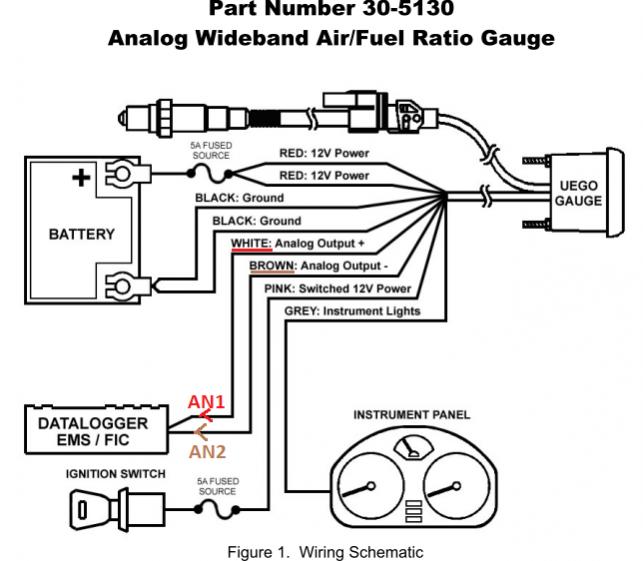 Source: busanabaseyya.blogspot.com
Kits, electronic controller adapters, and wiring connectors for skid steer loaders or bobcats are available. Autometer sport comp tach wiring. Each part ought to be placed and linked to different parts in specific way. This tachometer is factory calibrated for 8 cylinder engines. The tach must be returned to autometer for a light replacement.
 Source: ebay.com
Each component should be placed and connected with other parts in particular manner. The tachometer is designed to show the engine rpms or rotations per minute. Gauge can be mounted in a 21⁄ 16” dia. Pin on gauges car and truck parts a wiring diagram is a streamlined standard pictorial representation of an electrical circuit. Autometer gauge wiring diagram you ll need a comprehensive professional and easy to know wiring diagram.
 Source: sfxperformance.com
Gauge can be mounted in a 21 16 dia. Data logging output is included for one wire or two wire systems in both lambda or afr. Autometer gauge wiring diagram you ll need a comprehensive professional and easy to know wiring diagram. It’s intended to aid all the average person in developing a suitable method. Autometer wideband wiring diagram 11 12 2018 11 12 2018 3.
 Source: sfxperformance.com
Once you have selected a mounting location, you can run the four wires that. Autometer sport comp tach wiring. Evinrude trolling motor wiring diagram; Hey all i just found this site. Gauge can be mounted in a 21⁄ 16” dia.
 Source: ebay.com
Wiring connect the tachometer wires as shown. Sorry if it has been posted prior. Once you have selected a mounting location, you can run the four wires that. The speed sender signal range must be between 500 and 400 000 pulses mile 310 and 248 500 pulses km. Purchase from our online inventory today.
 Source: gautoparts.com
Each component ought to be set and linked to different parts in particular way. While pure gasoline has a stoichiometric ratio of 14.7:1, 10% ethanol with be 14.04:1. Lazy boy recliner spring diagram; Bare 1/4 of the end of the wire supplied at the sender unit. The tachometer is designed to show the engine rpms or rotations per minute.
This site is an open community for users to submit their favorite wallpapers on the internet, all images or pictures in this website are for personal wallpaper use only, it is stricly prohibited to use this wallpaper for commercial purposes, if you are the author and find this image is shared without your permission, please kindly raise a DMCA report to Us.
If you find this site serviceableness, please support us by sharing this posts to your preference social media accounts like Facebook, Instagram and so on or you can also bookmark this blog page with the title autometer wideband wiring diagram by using Ctrl + D for devices a laptop with a Windows operating system or Command + D for laptops with an Apple operating system. If you use a smartphone, you can also use the drawer menu of the browser you are using. Whether it’s a Windows, Mac, iOS or Android operating system, you will still be able to bookmark this website.


