Your Autometer electric fuel pressure gauge wiring diagram images are ready in this website. Autometer electric fuel pressure gauge wiring diagram are a topic that is being searched for and liked by netizens today. You can Find and Download the Autometer electric fuel pressure gauge wiring diagram files here. Get all free images.
If you’re searching for autometer electric fuel pressure gauge wiring diagram images information linked to the autometer electric fuel pressure gauge wiring diagram interest, you have come to the ideal blog. Our site frequently gives you suggestions for refferencing the highest quality video and image content, please kindly hunt and find more informative video content and images that fit your interests.
Autometer Electric Fuel Pressure Gauge Wiring Diagram. If you have this black box, this harness will not work. Nov 19, · auto meter oil pressure gauge wiring diagram in addition water temp gauge wiring diagram in addition vdo oil pressure gauge wiring diagram also saab engine oil moreover recalibrating the water temperature gauge together with stewart warner voltmeter wiring diagram also auto meter tachometer wiring diagram together with wiring diagram fuel sender and. Install an amp gauge in your car and you will instantly know the general condition of your vehicle�s electrical system. Sender grounds through threads black wire:
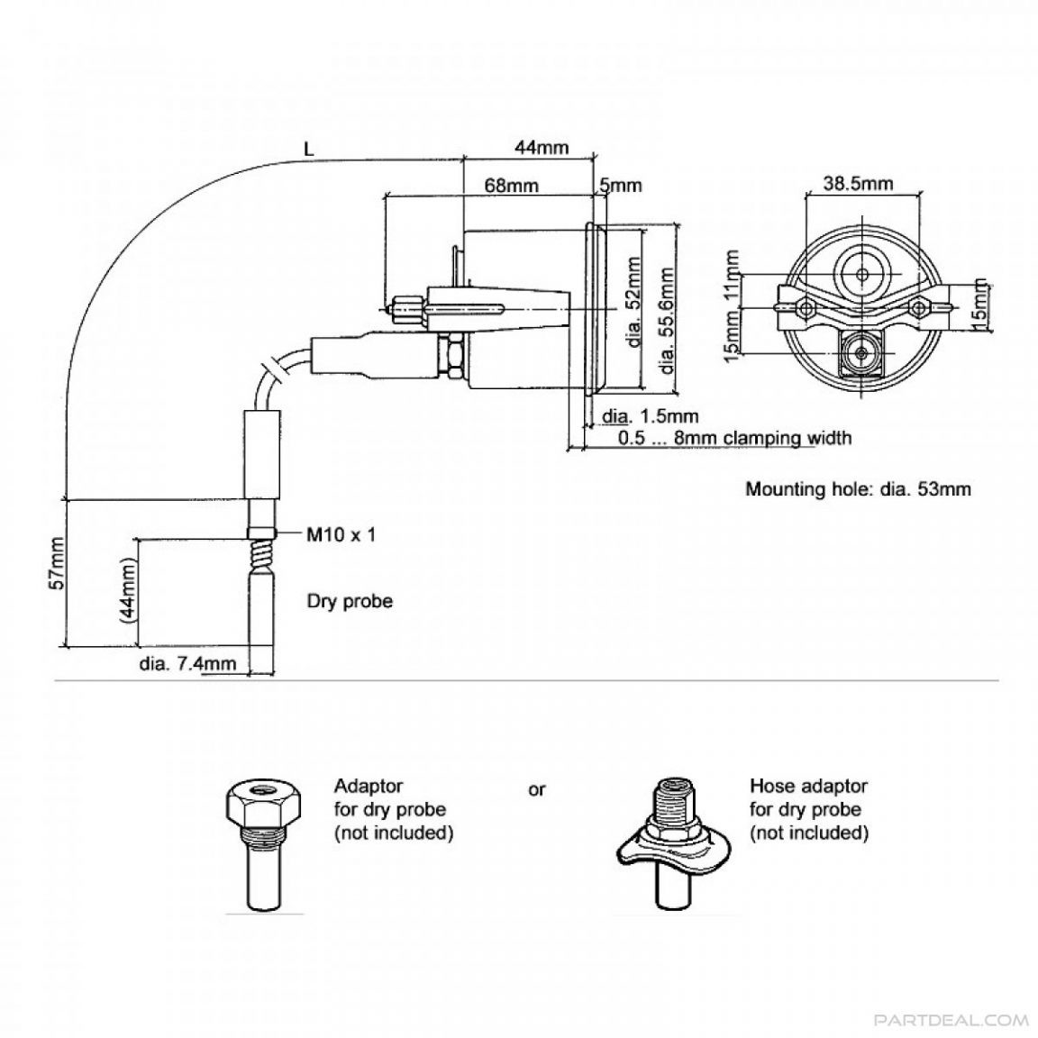 Autometer Oil Pressure Sensor Wiring Diagram 45900023 From schematron.org
There are just two things which are going to be present in any autometer gauge wiring diagram. We�ve been getting a lot of calls. Autometer oil pressure gauge wiring diagram. Another thing you will come across a circuit diagram could be traces. Autometer electric fuel pressure gauge wiring diagram. Gauge connects to fuel sender on fuel tank.
These guidelines will be easy to understand and apply.
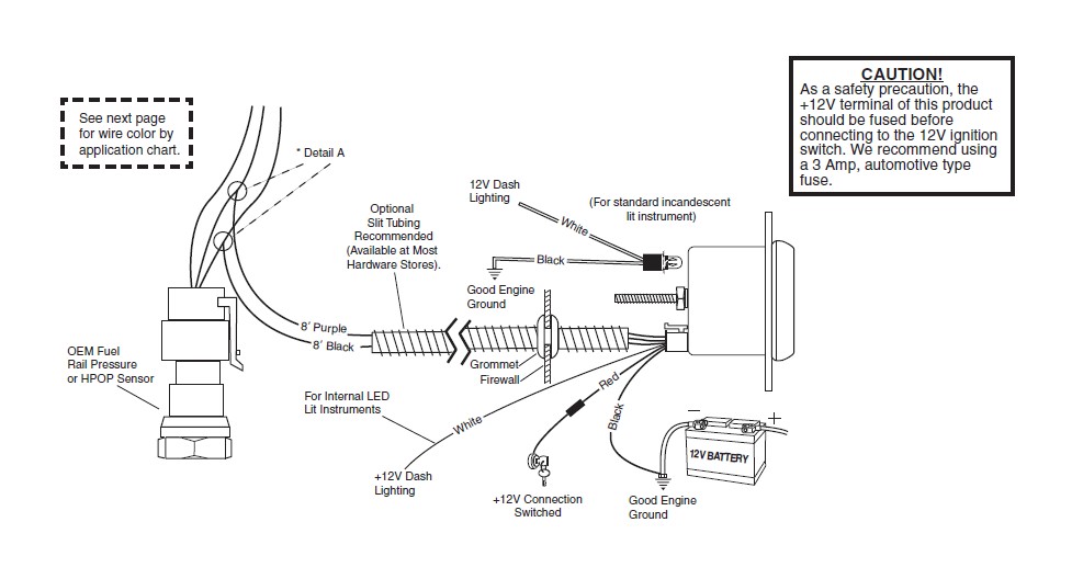
For fuel pressure gauge install the 1 8 npt pressure sender into the fuel system see caution below. Regulates voltage to 6 volts when 12 volts is applied. Connect one of the black wires to a good ground. Gauge (back view) wiring ground note: If not, the arrangement won’t function as it ought to be. So after being installed for over 3 years my oil pressure gauge stopped working.
 Source: diagramweb.net
Do not connect ohm meter to oxygen sensor, or touch wire to ground or power. Left is labeled �s�, signal wire from oil pressure or water temp sensor? Hole may have to be drilled, and adapter nut welded or brazed in pan. With this kind of an illustrative guide you are going to have the ability to troubleshoot avoid and total your projects easily. It’s intended to aid all the average person in developing a suitable method.
 Source: wholefoodsonabudget.com
If not, the arrangement won’t function as it ought to be. Gm 3 wire oil pressure switch wiring diagram. Left is labeled �s�, signal wire from oil pressure or water temp sensor? Connect one of the black wires to a good ground. (either black wire, does not matter which one) 7.
 Source: ricardolevinsmorales.com
If a new hole is drilled in the firewall a grommet is recommended. (the stock fuel level gauge, if equipped, must be disconnected.) 5. Connect to good ground or dimming circuits on some import vehicles gnd s i pressure gauges temperature gauges temperature sender use teflon sealing compound on pipe 1. Another thing you will come across a circuit diagram could be traces. So after being installed for over 3 years my oil pressure gauge stopped working.
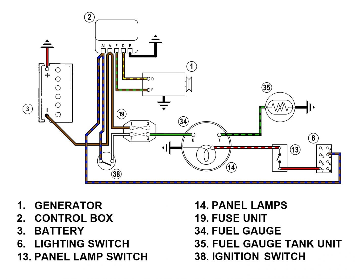 Source: mainetreasurechest.com
Connect one end to terminal post on fuel level sender and the opposite end to the sender (s) terminal spade on back of gauge. Left is labeled �s�, signal wire from oil pressure or water temp sensor? These guidelines will be easy to understand and apply. We�ve been getting a lot of calls. The lunar series fuel pressure may have been an earlier style gauge that used a secondary “black box” or module between the gauge head and sender.
 Source: easywiring.info
The lunar series fuel pressure may have been an earlier style gauge that used a secondary “black box” or module between the gauge head and sender. Angelo on october 3, 2021. Looking at the rear of the gauge, you will have 3 terminals labeled s, i, & gnd. Hole may have to be drilled, and adapter nut welded or brazed in pan. Install an amp gauge in your car and you will instantly know the general condition of your vehicle�s electrical system.
 Source: wirgrem.blogspot.com
Gauge connects to fuel sender on fuel tank. Hole may have to be drilled, and adapter nut welded or brazed in pan. If not, the arrangement won’t function as it ought to be. Autometer gauge wiring diagram you ll need a comprehensive professional and easy to know wiring diagram. Wiring diagram for autometer gauges.
 Source: wiringdiagram.2bitboer.com
It’s intended to aid all the average person in developing a suitable method. Diagram autometer electric oil pressure gauge wiring diagram full version hd quality wiring diagram toyotadiagrams andreapendibene it. Hole may have to be drilled and adapter nut (included) welded or brazed in pan. Gauge connects to fuel sender on fuel tank. The first component is emblem that indicate electric component in the circuit.
 Source: darandterry.blogspot.com
With this kind of an illustrative guide you are going to have the ability to troubleshoot avoid and total your projects easily. Connect the purple sender wire to the fuel level sender. Connect one of the black wires to a good ground. Hole may have to be drilled and adapter nut (included) welded or brazed in pan. Gm 3 wire oil pressure switch wiring diagram.
 Source: wiringdiagram.2bitboer.com
Left is labeled �s�, signal wire from oil pressure or water temp sensor? Auto meter electronic speedometer wiring diagram. So after being installed for over 3 years my oil pressure gauge stopped working. Gauge connects to fuel sender on fuel tank. Connect the white wire to dash lighting or switchable 12v light source.
![[DIAGRAM] Wiring Diagram For Autometer Oil Pressure Gauge [DIAGRAM] Wiring Diagram For Autometer Oil Pressure Gauge](https://wholefoodsonabudget.com/wp-content/uploads/2018/08/equus-gauge-wiring-diagram-autometer-voltmeter-wiring-diagram-best-equus-fuel-gauge-wiring-diagram-how-to-install-an-auto-10l.jpg) Source: geinokaigi.xyz
Source: geinokaigi.xyz
Make sure the nitrous bottle valve is closed and there is no So after being installed for over 3 years my oil pressure gauge stopped working. Regulates voltage to 6 volts when 12 volts is applied. Pictured below is a copy of the wiring diagram for the autometer oil pressure gauge. Auto meter electronic speedometer wiring diagram.
 Source: wiringdiagram.2bitboer.com
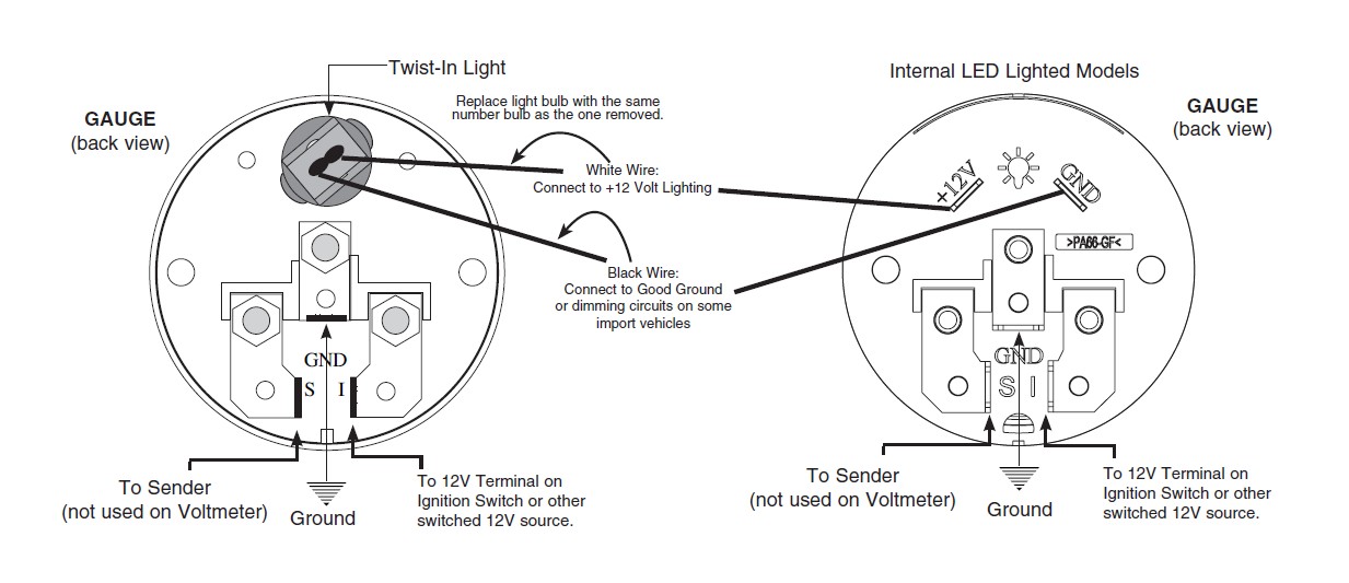
So after being installed for over 3 years my oil pressure gauge stopped working. Do not connect ohm meter to oxygen sensor, or touch wire to ground or power. Connect the white wire to dash lighting or switchable 12v light source, the red wire to switched +12v source and the black wire to ground. S = this connects to the sending unit in the fuel tank. Connect one of the black wires to a good ground.
 Source: ricardolevinsmorales.com
If you have this black box, this harness will not work. Connect the white wire to dash lighting or switchable 12v light source, the red wire to switched +12v source and the black wire to ground. Left is labeled �s�, signal wire from oil pressure or water temp sensor? If you’re not sure or acquired the gauge second hand, send us a picture of the front and back of the gauge along with. Purple sender wire to the fuel tank.
 Source: wholefoodsonabudget.com
Recommended auto meter hall effect sender 3 wire 16 pulses revolution. We�ve been getting a lot of calls. Autometer temperature gauge wiring diagram free download 2022 by kaia.schoen. Autometer oil pressure gauge wiring diagram wiring diagram is a simplified adequate pictorial representation of an electrical circuit it shows the components of the circuit as simplified shapes and the aptitude and signal associates in the midst of the devices. Make sure the nitrous bottle valve is closed and there is no
 Source: easywiring.info
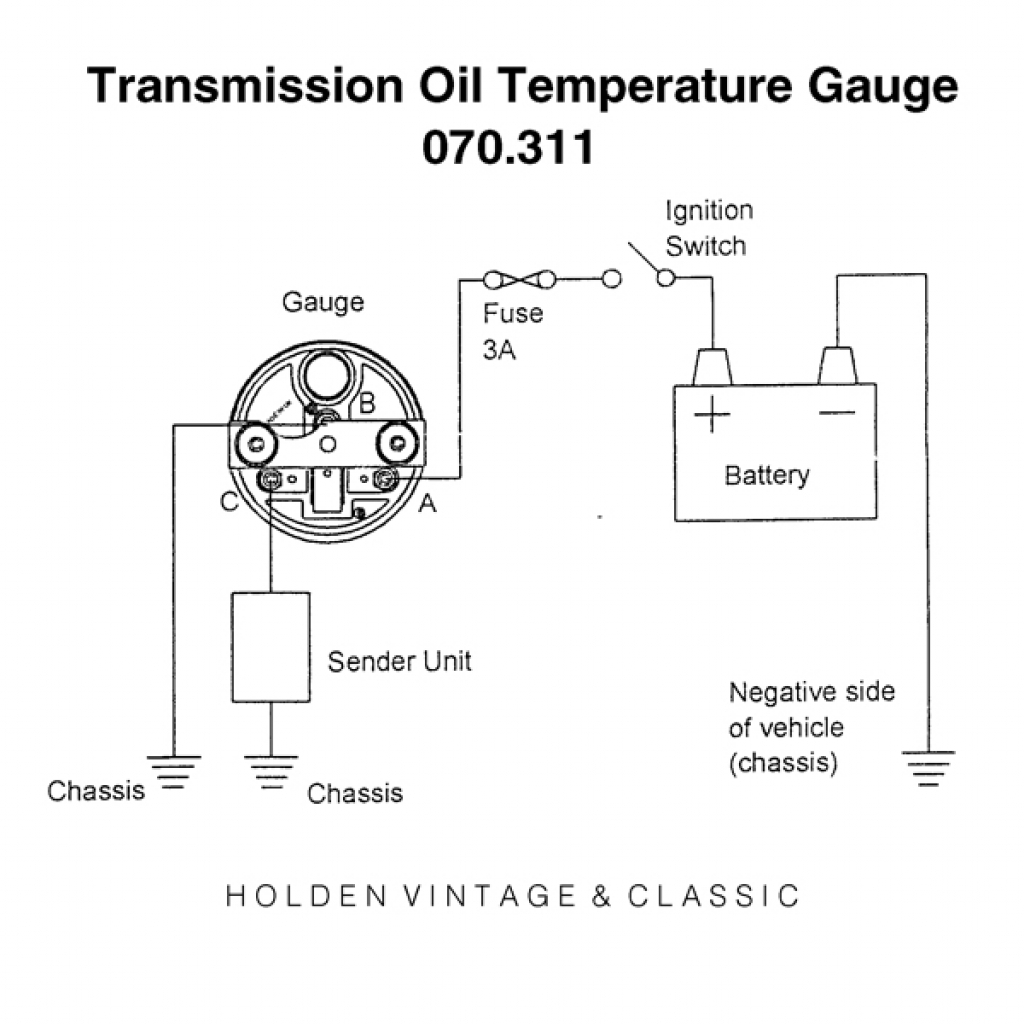
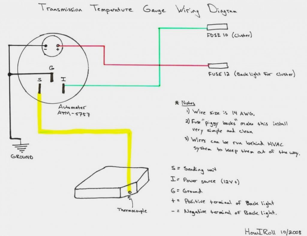
Hole may have to be drilled, and adapter nut welded or brazed in pan. Connect one end to terminal post on fuel level sender and the opposite end to the sender (s) terminal spade on back of gauge. Autometer sport comp tach wiring. Pictured below is a copy of the wiring diagram for the autometer oil pressure gauge. Looking at the rear of the gauge, you will have 3 terminals labeled s, i, & gnd.
 Source: wiringdiagram.2bitboer.com
Short sweep electric fuel level gauge 2650 1858 77 wiring. Existing wires may be used, or route proper length of 18 gage, wire from fuel tank to gauge. See speedo senders below for available auto meter senders the speedometer should be calibrated to ensure accurate operation after installation. Find the besttemplates at vincegray2014. If you have this black box, this harness will not work.

If a new hole is drilled in the firewall a grommet is recommended. Autometer gps speedometer installation and usage. Connect the purple sender wire to the fuel level sender. We�ve been getting a lot of calls. Gm 3 wire oil pressure switch wiring diagram.
 Source: melissappos.blogspot.com
Twist these two wires together and cover them with a layer of electrical tape. Each part ought to be placed and linked to different parts in specific way. Left is labeled �s�, signal wire from oil pressure or water temp sensor? Angelo on october 3, 2021. Autometer electric fuel pressure gauge wiring diagram.
 Source: schematron.org
Gm 3 wire oil pressure switch wiring diagram. [for oil pressure gauge installation, an optional 1⁄4” npt adapter. If not, the arrangement won’t function as it ought to be. Autometer gps speedometer installation and usage. Looking at the rear of the gauge, you will have 3 terminals labeled s, i, & gnd.
This site is an open community for users to do submittion their favorite wallpapers on the internet, all images or pictures in this website are for personal wallpaper use only, it is stricly prohibited to use this wallpaper for commercial purposes, if you are the author and find this image is shared without your permission, please kindly raise a DMCA report to Us.
If you find this site serviceableness, please support us by sharing this posts to your own social media accounts like Facebook, Instagram and so on or you can also save this blog page with the title autometer electric fuel pressure gauge wiring diagram by using Ctrl + D for devices a laptop with a Windows operating system or Command + D for laptops with an Apple operating system. If you use a smartphone, you can also use the drawer menu of the browser you are using. Whether it’s a Windows, Mac, iOS or Android operating system, you will still be able to bookmark this website.


