Your Autometer air fuel ratio gauge wiring diagram images are available in this site. Autometer air fuel ratio gauge wiring diagram are a topic that is being searched for and liked by netizens now. You can Find and Download the Autometer air fuel ratio gauge wiring diagram files here. Find and Download all free vectors.
If you’re searching for autometer air fuel ratio gauge wiring diagram images information linked to the autometer air fuel ratio gauge wiring diagram topic, you have visit the right site. Our website always gives you hints for viewing the maximum quality video and picture content, please kindly search and find more enlightening video articles and images that fit your interests.
Autometer Air Fuel Ratio Gauge Wiring Diagram. Do not connect ohm meter to oxygen sensor, or touch wire to ground or power. 41 autometer fuel gauge wiring diagram get link; The difference between these two types is that a wideband air fuel gauge gives you information from the internal combustion chamber while the narrowband uses your car’s factory oxygen sensor to show its. With this kind of an illustrative guide, you are going to have the ability to troubleshoot, avoid, and complete your tasks with ease.
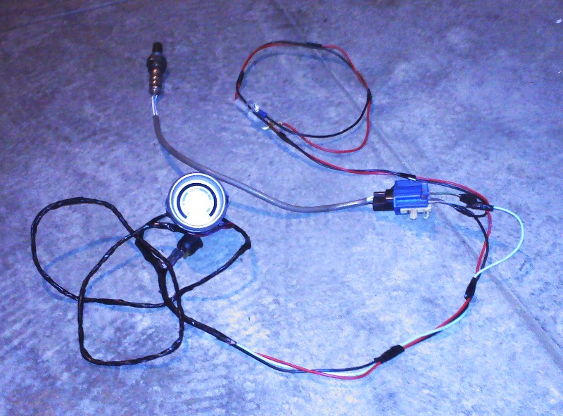 Autometer Wideband Wiring Diagram From schematron.org
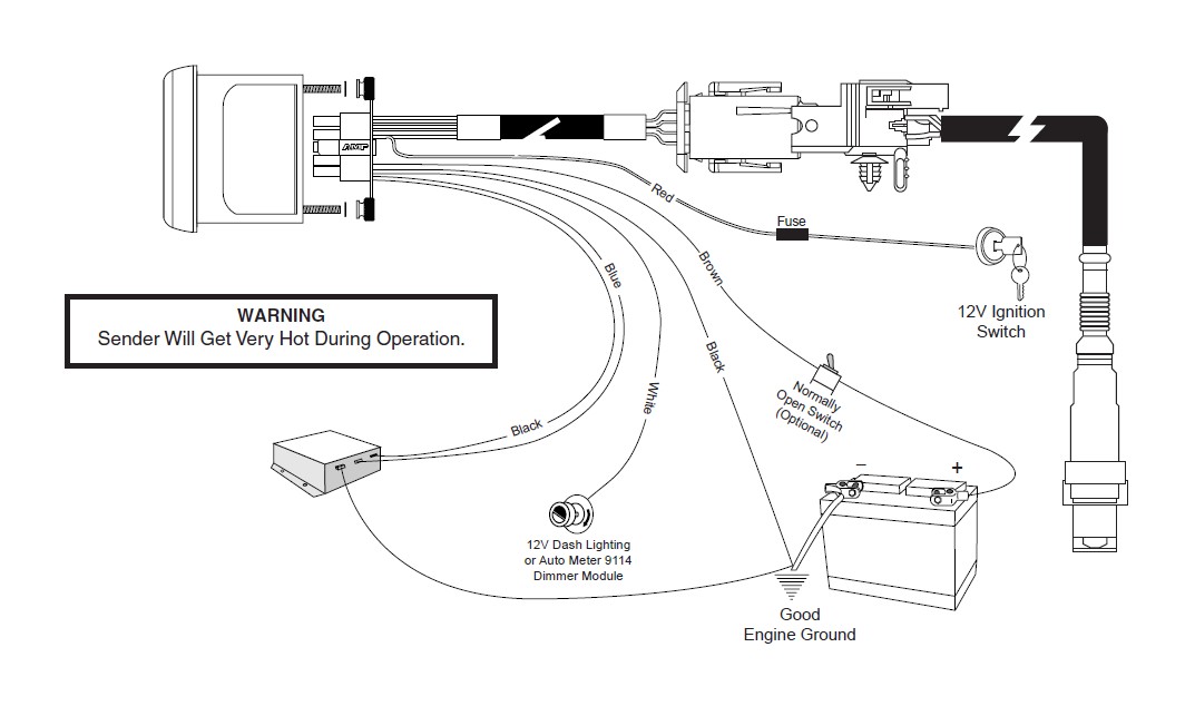
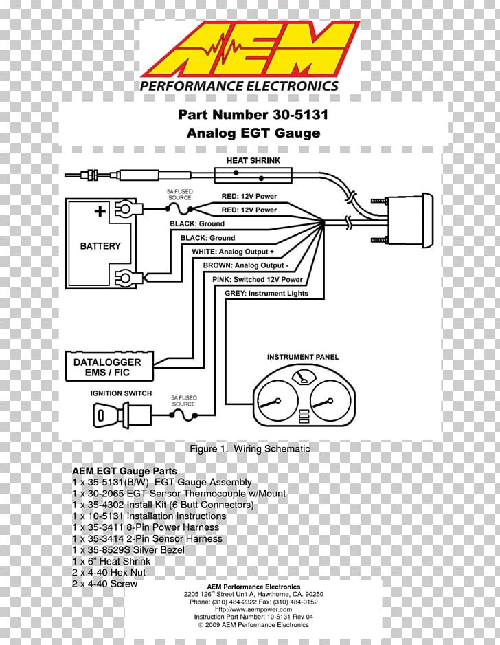
Gauge can be mounted in a 21 ⁄16 dia. Connect to a fused and switched 12v positive source that is turned on and off with the ignition switch. 12v ignition switch good engine ground Autometer boost gauge wiring diagram. If you would like to put the gauge into the dash, cut a hole in the dash the same size as your air fuel gauge using a. Autometer air fuel ratio gauge wiring diagram have a graphic from the other.
Autometer air fuel ratio gauge wiring diagram it also will feature a picture of a kind that might be observed in the gallery of autometer air fuel ratio gauge wiring diagram.
May 22, 2021 on autometer electric fuel pressure gauge wiring diagram. Step 1 use the wiring diagram and test light or multi meter to locate the positive wire from the alternator to the fuse block. The collection that comprising chosen picture and the best amongst others. January 7, 2019 april 12, 2020. An initial look at a circuit layout may be complex but if you could check out a. Autometer air fuel ratio gauge wiring diagram it also will feature a picture of a kind that might be observed in the gallery of autometer air fuel ratio gauge wiring diagram.
![[DIAGRAM] Autometer Fuel Gauge Wiring Diagram FULL Version [DIAGRAM] Autometer Fuel Gauge Wiring Diagram FULL Version](https://www.soundingsonline.com/.image/t_share/MTQ5Nzk4MTg3ODcwMjAxMjQ1/gauge-fuel-62618.jpg) Source: kingsage.cheminsdetablemagazine.fr
Source: kingsage.cheminsdetablemagazine.fr
Additionally, wiring diagram provides you with enough time frame by which the assignments are to be accomplished. Autometer air fuel ratio gauge wiring diagram the purpose of this article we ll be installing a narrowband air fuel ratio gauge from autometer otherwise known as the blinky light pdf document / selasa, 07. The collection that comprising chosen picture and the. Autometer air fuel ratio gauge wiring diagram have a graphic from the other. By vallery masson on may 22, 2021.
 Source: wiringdiagramsx.blogspot.com
Autometer air fuel ratio gauge wiring diagram it also will feature a picture of a kind that might be observed in the gallery of autometer air fuel ratio gauge wiring diagram. With this kind of an illustrative guide, you are going to have the ability to troubleshoot, avoid, and complete your tasks with ease. Components available on your auto meter wideband air fuel gauge. The collection that comprising chosen picture and the. Autometer air fuel ratio gauge wiring diagram the purpose of this article we ll be installing a narrowband air fuel ratio gauge from autometer otherwise known as the blinky light pdf document / selasa, 07.

Put the mounting kit on the specific place you want it and drill the screws that came with the mounting kit into the dash. Put the mounting kit on the specific place you want it and drill the screws that came with the mounting kit into the dash. The purpose of an afr gauge is to measure the air to fuel ratio of your engine. Autometer boost gauge wiring diagram. Step 1 use the wiring diagram and test light or multi meter to locate the positive wire from the alternator to the fuse block.
 Source: diagramweb.net
41 autometer fuel gauge wiring diagram get link; Home » autometer wiring diagram : For fuel pressure gauge install the 1 8 npt pressure sender into the fuel system see caution below. Autometer electric fuel pressure gauge wiring diagram. Connect to a fused and switched 12v positive source that is turned on and off with the ignition switch.

Autometer sport comp analog gauges 3579. These fascinating plants are found growing on trees and rocks in the. Connect to a fused and switched 12v positive source that is turned on and off with the ignition switch. Do not connect ohm meter to oxygen sensor, or touch wire to ground or power. Autometer boost gauge wiring diagram.
 Source: americanmuscle.com
The air/fuel ratio monitor has 20 led�s. Autometer air fuel gauge wiring diagram pro p tach wiring diagram maipinineh pro p tach wiring diagram operates on 4 6 or 8 cylinder engines with points electronic and most 12v high performance racing ignitions pro p tach chart. Autometer boost gauge wiring diagram. The air fuel gauge should come with a mounting kit that will allow you to put the gauge on top of the dash. Step 1 use the wiring diagram and test light or multi meter to locate the positive wire from the alternator to the fuse block.
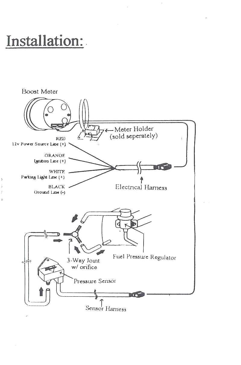 Source: wiringdiagramsx.blogspot.com
Additionally, wiring diagram provides you with enough time frame by which the assignments are to be accomplished. Additionally, wiring diagram provides you with enough time frame by which the assignments are to be accomplished. You will be able to learn exactly once the projects should be completed, that makes it easier for you to correctly manage your time. Autometer air fuel ratio gauge wiring diagram the purpose of this article we ll be installing a narrowband air fuel ratio gauge from autometer otherwise known as the blinky light pdf document / selasa, 07. They are so many great picture list that could become your motivation and informational purpose of air fuel ratio gauge wiring diagram design ideas for your own collections.
 Source: wiring89.blogspot.com
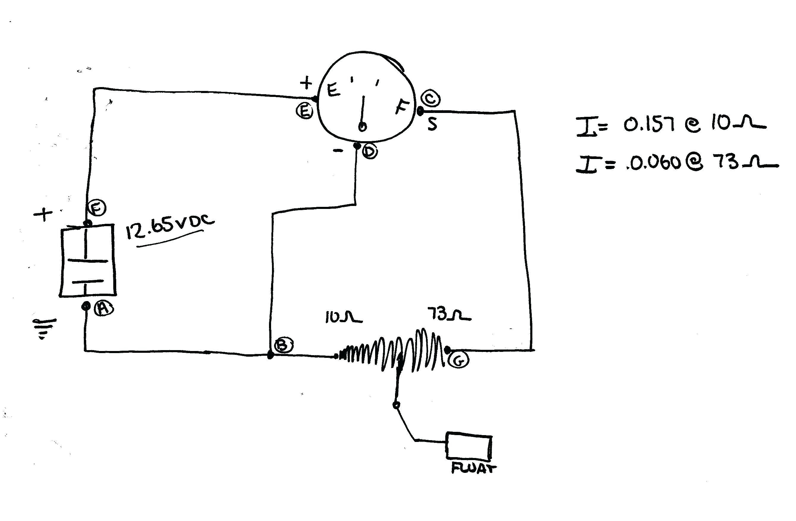
If you would like to put the gauge into the dash, cut a hole in the dash the same size as your air fuel gauge using a. Press the gauge into the mounting kit. Connect one end to terminal post on fuel level sender and the opposite end to the sender s terminal spade on back of gauge. Autometer sport comp analog gauges 3579. Connect to a fused and switched 12v positive source
 Source: schematron.org
Gauge can be mounted in a 21 ⁄16 dia. By vallery masson on may 22, 2021. The auto meter air/fuel gauge has a signal output for supplying information to a data logger or engine management system. The collection that comprising chosen picture and the best amongst others. The air/fuel ratio monitor has 20 led�s.
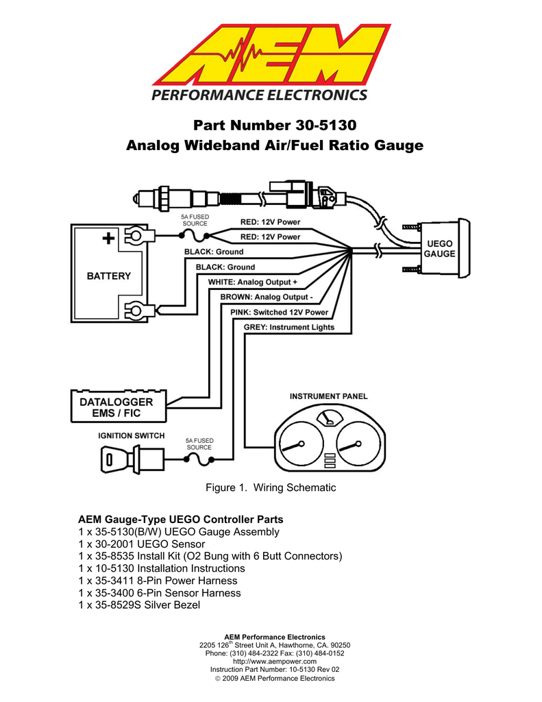 Source: cars-trucks24.blogspot.com
The air fuel gauge should come with a mounting kit that will allow you to put the gauge on top of the dash. Connect one end to terminal post on fuel level sender and the opposite end to the sender s terminal spade on back of gauge. Autometer sport comp analog gauges 3579. 0 volts out equals 10.0 air/fuel ratio, 4 volts out equals 18.0 air/fuel ratio. Press the gauge into the mounting kit.
 Source: smarts4k.com
An initial look at a circuit layout may be complex but if you could check out a. Autometer air fuel ratio gauge wiring diagram have a graphic from the other. With this kind of an illustrative guide, you are going to have the ability to troubleshoot, avoid, and complete your tasks with ease. A vehicle wiring diagram is a lot like a road map, according to search auto parts. Do not connect ohm meter to oxygen sensor, or touch wire to ground or power.
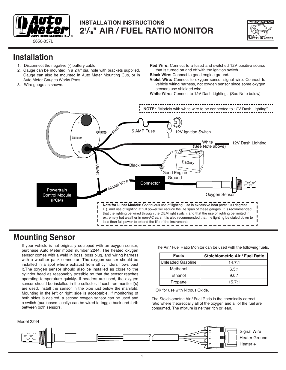 Source: manualsdir.com
Components available on your auto meter wideband air fuel gauge. The a/f ratio meter is a voltmeter with a range of 0 to 1 volt. Additionally, wiring diagram provides you with enough time frame by which the assignments are to be accomplished. Autometer air fuel gauge wiring diagram have an image associated with the other. Gauge connects to fuel sender on fuel tank.
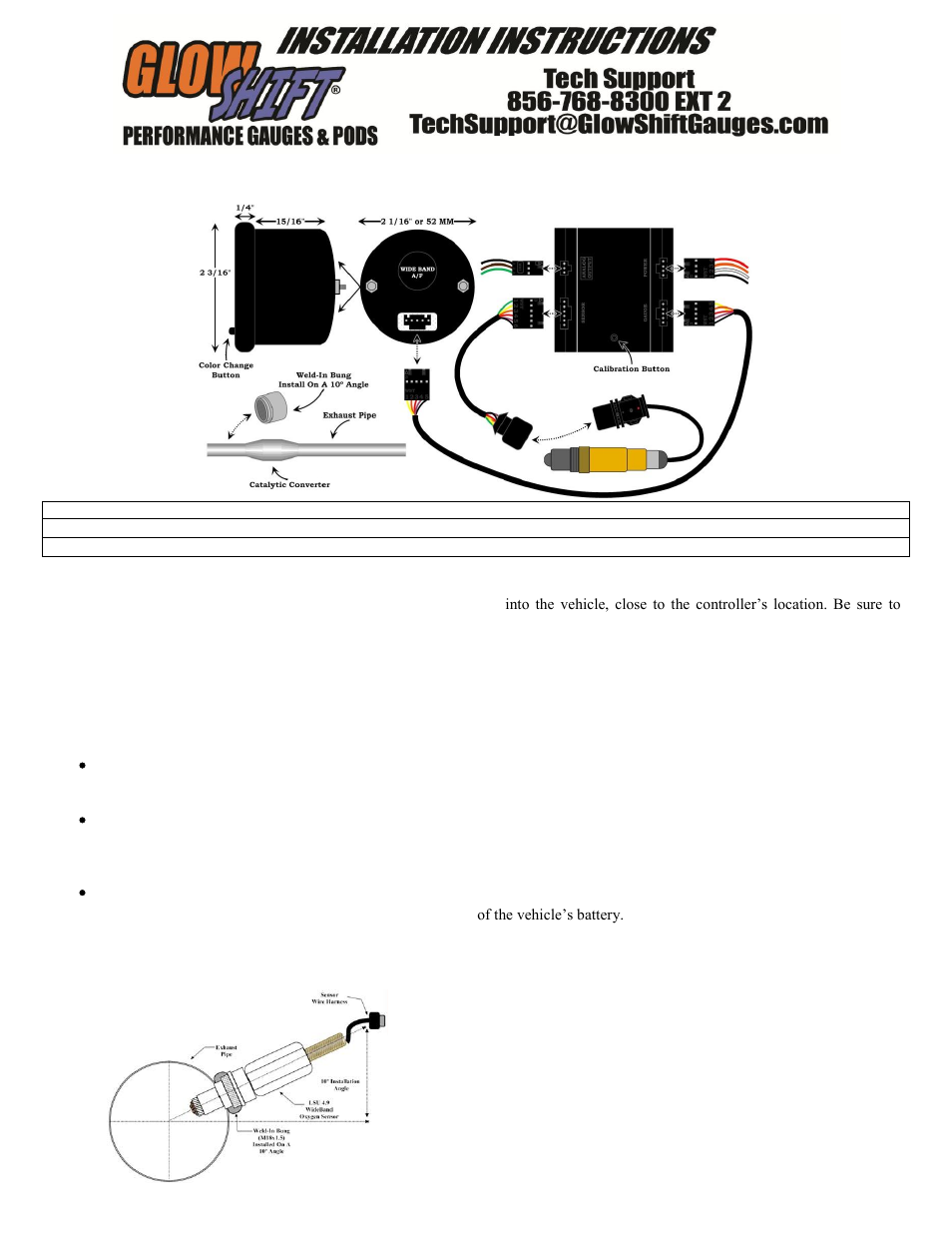 Source: wiringdiagramsx.blogspot.com
By vallery masson on may 22, 2021. Do not connect ohm meter to oxygen sensor, or touch wire to ground or power. Gauge can also be mounted in auto meter mounting cup, or in auto meter gauge works pods. Air / fuel ratio meter and oxygen sensor operation. Connect to a fused and switched 12v positive source

With this kind of an illustrative guide, you are going to have the ability to troubleshoot, avoid, and complete your tasks with ease. Hopefully you are all enjoy and finally will get the best picture from our collection that submitted here and also use for suited needs for personal use. Gauge can be mounted in a 21⁄ 16 dia. There are two air fuel gauge options to choose from: May 22, 2021 on autometer electric fuel pressure gauge wiring diagram.
 Source: whatmindsaid.blogspot.com
There are two air fuel gauge options to choose from: Connect to a fused and switched 12v positive source Gauge can also be mounted in auto meter mounting cup, or in auto meter gauge works pods. Autometer air fuel gauge wiring diagram pro p tach wiring diagram maipinineh pro p tach wiring diagram operates on 4 6 or 8 cylinder engines with points electronic and most 12v high performance racing ignitions pro p tach chart. An initial look at a circuit layout may be complex but if you could check out a.
 Source: wiringdiagramsx.blogspot.com
The a/f ratio meter is a voltmeter with a range of 0 to 1 volt. For newer plus wideband afr gauge models please use part number 5317. Gauge can also be mounted in auto meter mounting cup, or in auto meter gauge works pods. Autometer gs electrical air fuel ratio gauge 2 1 16 dia black face 3870 gauges premium cars pressure gauge. The difference between these two types is that a wideband air fuel gauge gives you information from the internal combustion chamber while the narrowband uses your car’s factory oxygen sensor to show its.
 Source: wiringdiagramsx.blogspot.com
Gauge can also be mounted in auto meter mounting cup or in auto meter gauge works pods. Additionally, wiring diagram provides you with enough time frame by which the assignments are to be accomplished. Auto meter gauges installation instructions installing an air fuel ratio gauge autometer air fuel gauge wiring diagram 41 autometer fuel gauge wiring diagram get link; Autometer air fuel gauge wiring diagram it also will include a picture of a kind that could be observed in the gallery of autometer air fuel gauge wiring diagram.

With this kind of an illustrative guide, you are going to have the ability to troubleshoot, avoid, and complete your tasks with ease. An initial look at a circuit layout may be complex but if you could check out a. Air / fuel ratio meter and oxygen sensor operation. One led lights up for every 50mv of oxygen sensor output. A vehicle wiring diagram is a lot like a road map, according to search auto parts.
This site is an open community for users to submit their favorite wallpapers on the internet, all images or pictures in this website are for personal wallpaper use only, it is stricly prohibited to use this wallpaper for commercial purposes, if you are the author and find this image is shared without your permission, please kindly raise a DMCA report to Us.
If you find this site convienient, please support us by sharing this posts to your favorite social media accounts like Facebook, Instagram and so on or you can also save this blog page with the title autometer air fuel ratio gauge wiring diagram by using Ctrl + D for devices a laptop with a Windows operating system or Command + D for laptops with an Apple operating system. If you use a smartphone, you can also use the drawer menu of the browser you are using. Whether it’s a Windows, Mac, iOS or Android operating system, you will still be able to bookmark this website.

