Your Automatic water level controller wiring diagram images are available in this site. Automatic water level controller wiring diagram are a topic that is being searched for and liked by netizens today. You can Find and Download the Automatic water level controller wiring diagram files here. Find and Download all royalty-free photos and vectors.
If you’re searching for automatic water level controller wiring diagram pictures information related to the automatic water level controller wiring diagram keyword, you have visit the ideal site. Our website frequently gives you suggestions for seeking the highest quality video and picture content, please kindly search and locate more informative video content and graphics that match your interests.
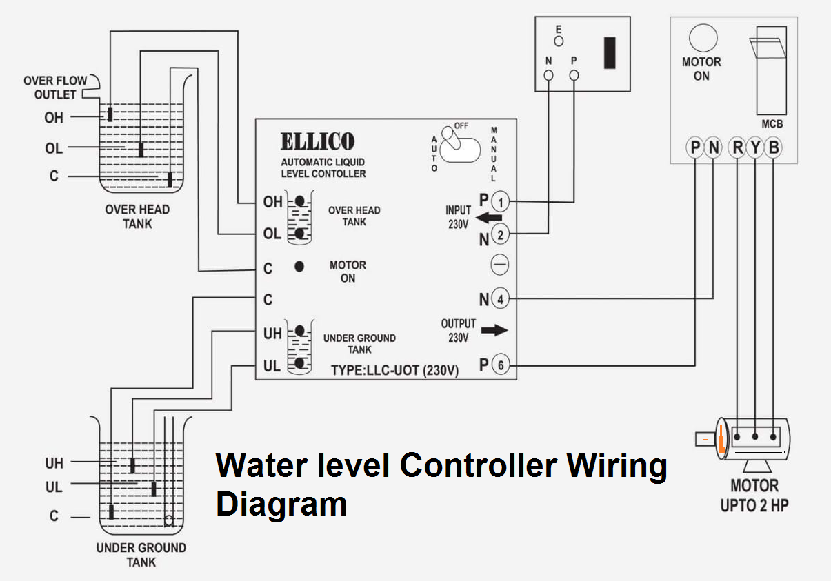
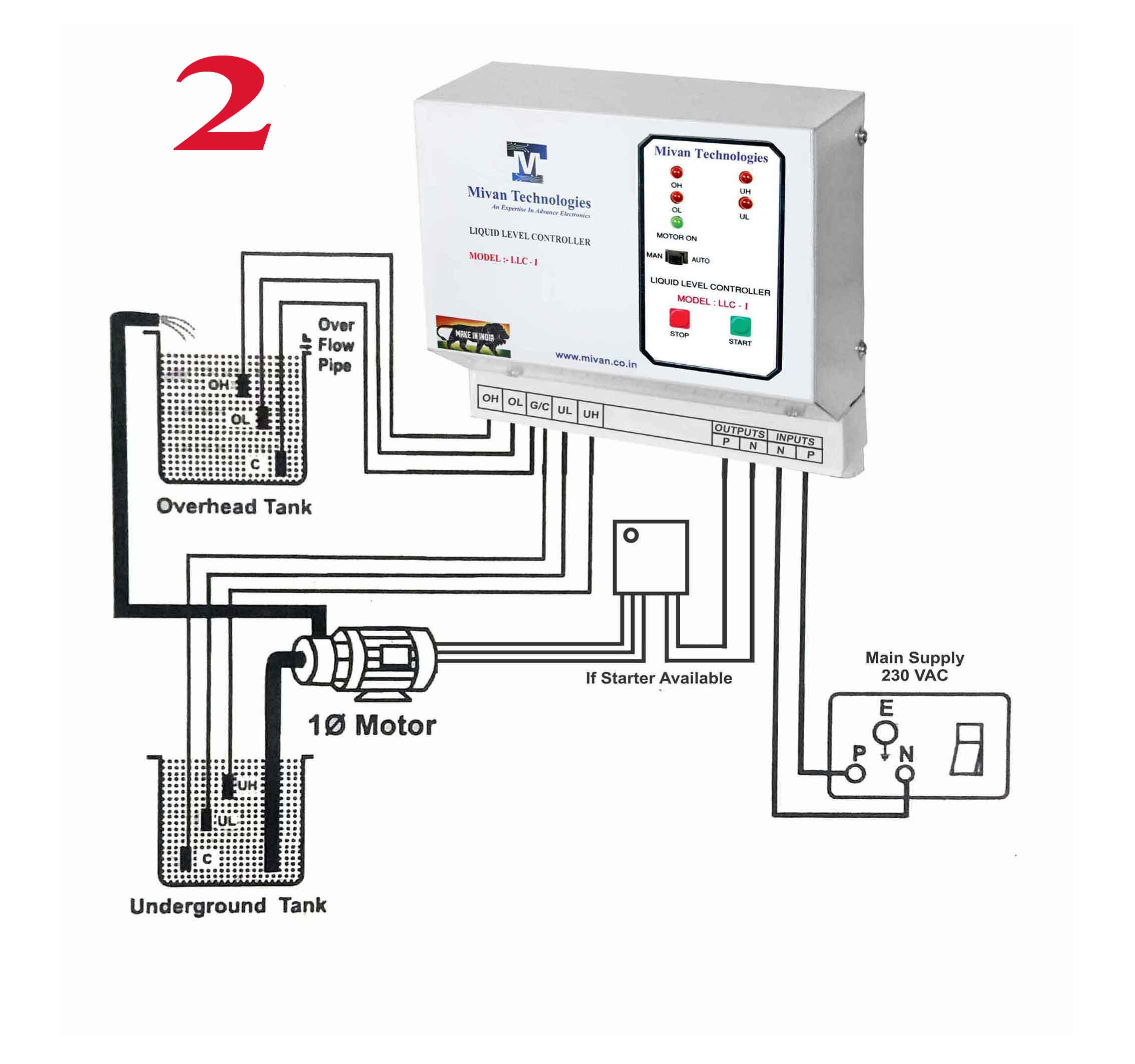
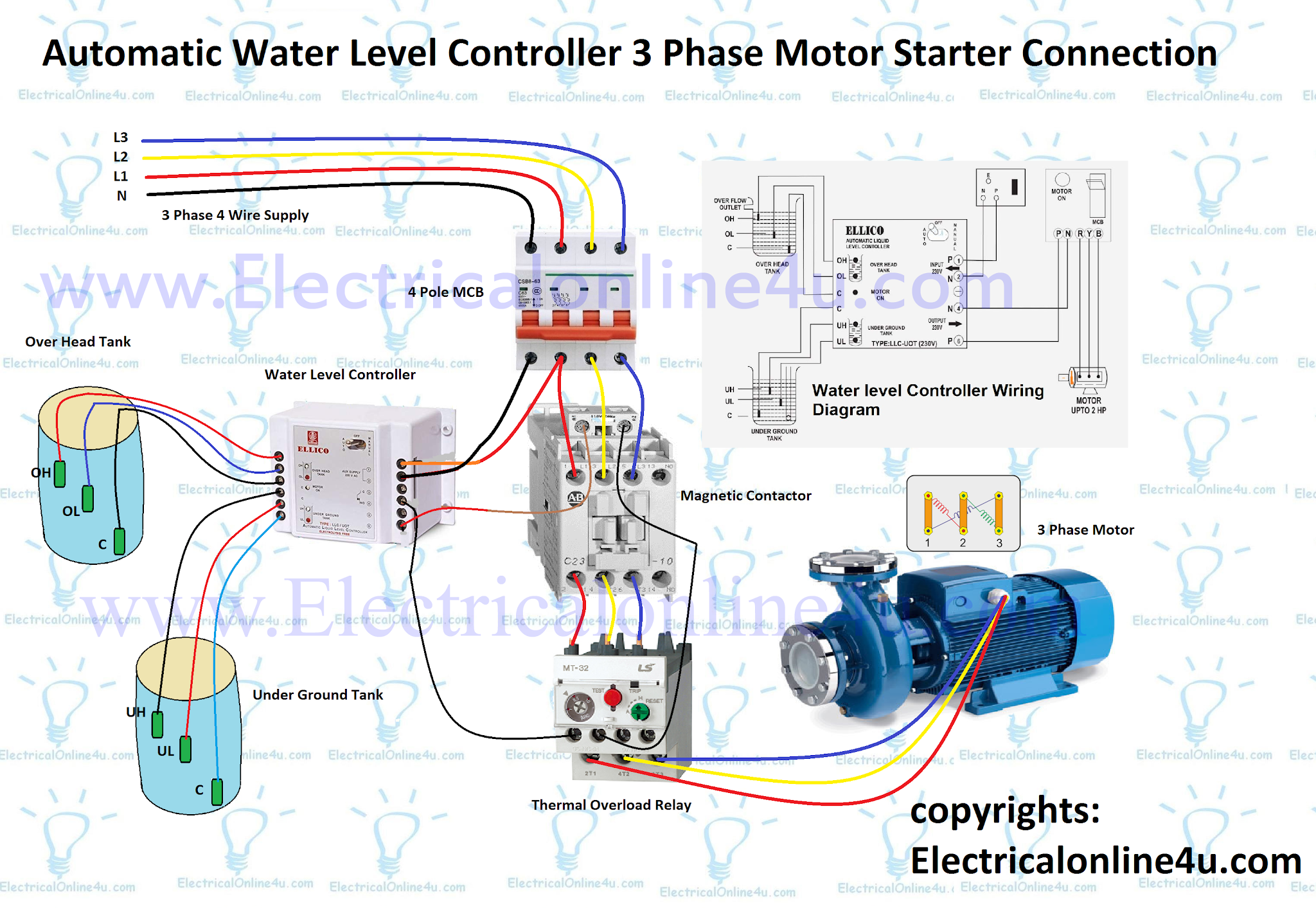
Automatic Water Level Controller Wiring Diagram. Insulated aluminium wires can be used as the probes. Water level controller circuit diagram probe arrangement diagram the probes can be arranged as shown in the diagram above. Problem statement the traditional fluid level control tank had many disadvantage such as; When there is enough water in the underground tank, probes c and s are connected through water.
 3 Phase DOL Starter Control and Power Wiring Diagram From youtube.com
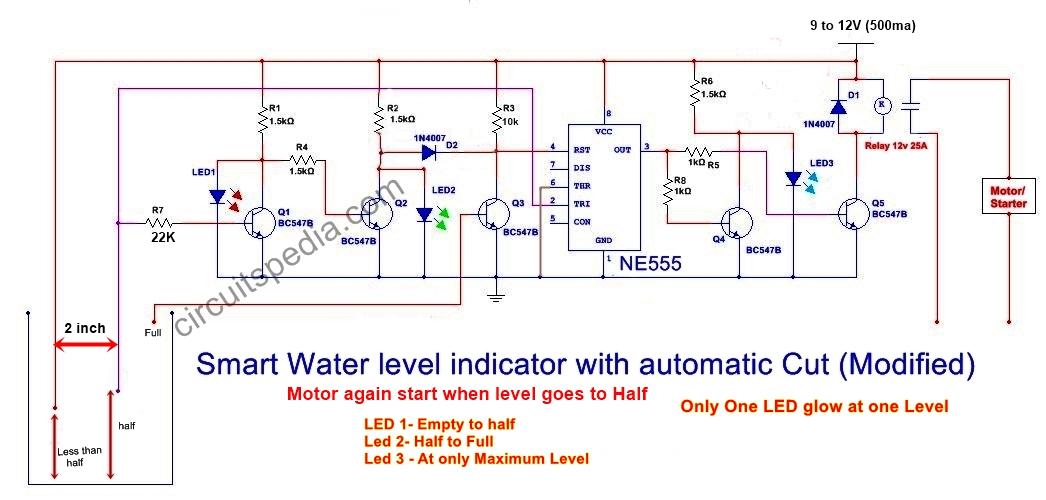
The circuit uses 6 transistors, 1 ne555 timer ic, a relay and few passive components. An automatic regulator suitable for water level sensing and control was developed by [5] using the mc14066 integrated circuit. Whenever tank gets filled, the motor switches off. Automatic water level controller circuit is a simple engineering project. Here we have created 3 levels (main, low, high), we can create alarms and. Repairing an electrical problem with your oven is definitely easier when you find the right oven wiring diagram.
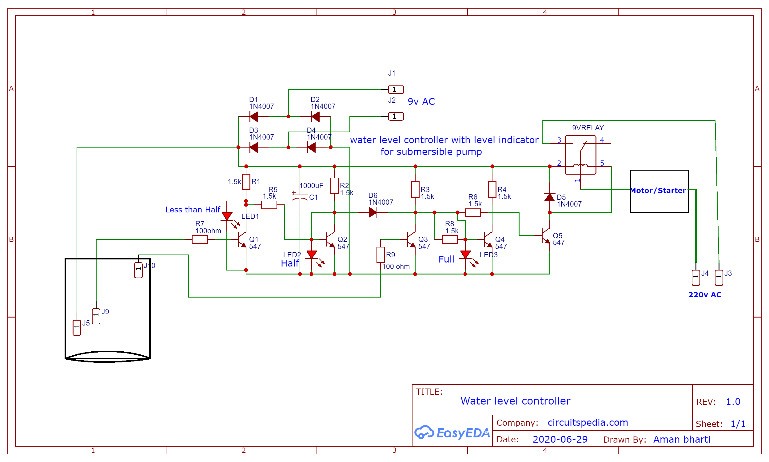
So current through r5 and d1 to trigger base of q3, cause q3 conducts current to cause the transistor q4 also works.
This enabled the entire circuit to function as a. Problem statement the traditional fluid level control tank had many disadvantage such as; And motor starts to fill the tank. Whenever tank gets filled, the motor switches off. Automatic water level controller circuit diagram for submersible pump single phase 3 phase in the above automatic water level controller for tank wiring diagram. This article will show you how to monitor and manage the amount of water in.
 Source: electricalonline4u.com
When q4 conducts current, led1 will get a forward biased. Automatic water level controller circuit is a simple engineering project. Problem statement the traditional fluid level control tank had many disadvantage such as; It can automatically switch on and off the domestic water pump set depending on the tank water level. The water level controller circuits are used in the factories, chemical plants, and electrical substations and also in other liquid storage systems.
 Source: homemade-circuits.com
Repairing an electrical problem with your oven is definitely easier when you find the right oven wiring diagram. Figure 1 simple automatic water level controller circuit. Float switch wiring automatic manual single phase water pump controller water pump youtube electrical circuit diagram water level switch water pumps. Each sensors float is suspended from above using an aluminium rod. When the level of water has reached half level and touches the middle wire of tank then the current from vcc supply through the water goes to base terminal of transistor q1 and this will turn on.
 Source: wiringview.co
The motor will also switch. You can implement this motor driver circuit at your home or college using less costly components. Automatic water level controllers switch the motor on whenever the water level drops below a certain level and shuts the motor off when the water rises well above a fixed level. It can automatically switch on and off the domestic water pump set depending on the tank water level. Automatic water level controller wiring diagram for 3 phase motor submersible pump submersible pump water pump motor electrical installation.
 Source: tacoma-wiring-diagram.blogspot.com
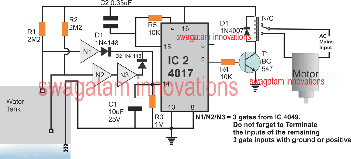
Float switch wiring automatic manual single phase water pump controller water pump youtube electrical circuit diagram water level switch water pumps. By sensing the water level in a tank, the water level controller utilising 8051 microcontroller project will assist in automatically managing the water motor. The circuit is completely automatic which starts the pump motor when the water level in the over head tank goes We know the property of 555 timer ic, i.e. The motor will also switch.
 Source: youtube.com
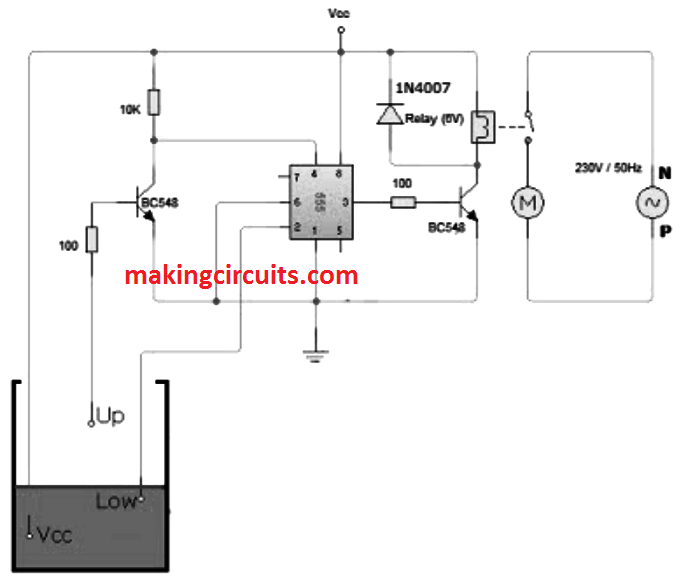
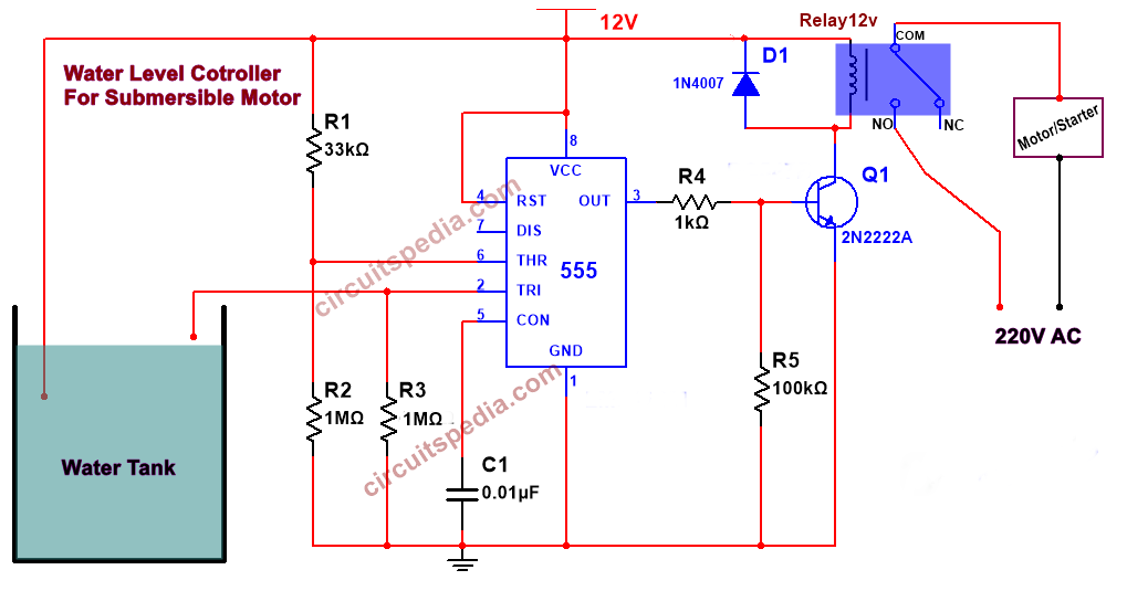
As we have kept h terminal at the bottom of the tank, when water level falls below l terminal timer ic is triggered at pin 2, because of this output pin 3 goes high and energizes the relay and motor connected to it become “on”. A wiring diagram is a. Water level controller circuit description. Figure 1 simple automatic water level controller circuit. You can implement this motor driver circuit at your home or college using less costly components.
 Source: circuitdiagramcentre.blogspot.com
A simple but very reliable and effective water level controller circuit diagram is shown here. This simple transistor based water level controller circuit is very useful to indicate the water levels in a tank. 3 phase submersible pump wiring diagram with dol stater electrical online 4u. Each sensors float is suspended from above using an aluminium rod. Automatic water level controller wiring diagram for 3 phase motor submersible pump submersible pump water pump motor electrical installation.
 Source: wiringview.co
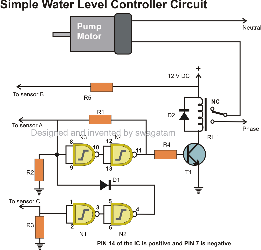
As a result, transistor t1 gets forward biased and starts conducting. Wiring diagram for 220 volt submersible pump bookingritzcarlton info in 2021 submersible well. The approximated cost of the project is about $5 only. As a result, transistor t1 gets forward biased and starts conducting. Whenever tank gets filled, the motor switches off.
 Source: homemade-circuits.com
The motor will also switch. Water pump relay controller circuit schematic diagram. Automatic water level controller circuit diagram for submersible pump single phase 3 phase in the above automatic water level controller for tank wiring diagram. In this project 3 wires are dipped in water tank. The probes can be binded on a plastic rod and should be erected vertically inside the tank.
 Source: youtube.com
Wiring diagram for 220 volt submersible pump bookingritzcarlton info in 2021 submersible well. And motor starts to fill the tank. The water level controller circuits are used in the factories, chemical plants, and electrical substations and also in other liquid storage systems. Figure 1 simple automatic water level controller circuit. As a result, transistor t1 gets forward biased and starts conducting.
 Source: circuitspedia.com
Water level controller circuit description. Each sensors float is suspended from above using an aluminium rod. Water level controller circuit description. You can implement this motor driver circuit at your home or college using less costly components. As a result, transistor t1 gets forward biased and starts conducting.
 Source: electricalonline4u.com
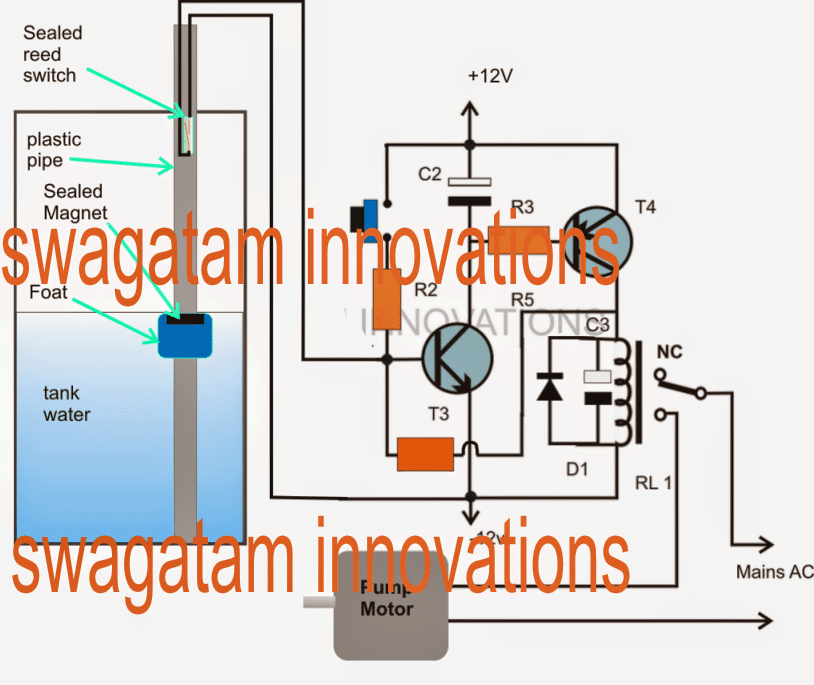
Water pump relay controller circuit schematic diagram. You can implement this motor driver circuit at your home or college using less costly components. This simple transistor based water level controller circuit is very useful to indicate the water levels in a tank. This arrangement is encased in a pvc pipe and fixed vertically on the inside wall of the water tank. Here we have created 3 levels (main, low, high), we can create alarms and.
 Source: tacoma-wiring-diagram.blogspot.com
Automatic water level controller circuit is a simple engineering project. A wiring diagram is a. Each sensors float is suspended from above using an aluminium rod. The controller responds depending upon the relevant levels of water in the tank and the position of the immersed sensor points. Automatic water level controller circuit is a simple engineering project.
 Source: ebay.in
As a result, transistor t1 gets forward biased and starts conducting. Automatic water level controller circuit is a simple engineering project. As we have kept h terminal at the bottom of the tank, when water level falls below l terminal timer ic is triggered at pin 2, because of this output pin 3 goes high and energizes the relay and motor connected to it become “on”. Transistor q1 is connected as not logic circuit , so when the input of this on the base is +ve (on) then the output at collector terminal will be low (off), in this case only led 2. The water level controller circuits are used in the factories, chemical plants, and electrical substations and also in other liquid storage systems.
 Source: rolexswitchgears.com
When the level of water has reached half level and touches the middle wire of tank then the current from vcc supply through the water goes to base terminal of transistor q1 and this will turn on. Here we have created 3 levels (main, low, high), we can create alarms and. Automatic water level controller wiring diagram for 3 phase motor submersible pump submersible pump water pump motor electrical installation. So current through r5 and d1 to trigger base of q3, cause q3 conducts current to cause the transistor q4 also works. Also we can reset back the ic by applying a low voltage at the 4th pin (reset pin).
 Source: circuitdiagramcentre.blogspot.com
Simple water level indicator circuits schematic of alarm circuit diagram easy electronics projects with buzzer sensor or liquid detector full using 7 segment system automatic controller ic uln2003 working anti corrossive probe arduino numeric 2 for submersible 555 timer 1 12 stage how works the stop tank overflow wireless atmega32 avr hot You can implement this motor driver circuit at your home or college using less costly components. This arrangement is encased in a pvc pipe and fixed vertically on the inside wall of the water tank. So current through r5 and d1 to trigger base of q3, cause q3 conducts current to cause the transistor q4 also works. As we have kept h terminal at the bottom of the tank, when water level falls below l terminal timer ic is triggered at pin 2, because of this output pin 3 goes high and energizes the relay and motor connected to it become “on”.
 Source: diary-of-electric.blogspot.com
As a result, transistor t1 gets forward biased and starts conducting. A simple but very reliable and effective water level controller circuit diagram is shown here. We know the property of 555 timer ic, i.e. Whenever tank gets filled, the motor switches off. Water pump relay controller circuit schematic diagram.
 Source: youtube.com
And motor starts to fill the tank. Its output goes high when voltage at the second pin(trigger pin) is less than 1/3 vcc. And motor starts to fill the tank. Automatic water level controller wiring diagram for 3 phase motor submersible pump submersible pump water pump motor electrical installation. So current through r5 and d1 to trigger base of q3, cause q3 conducts current to cause the transistor q4 also works.
 Source: waterlevelcontrols.com
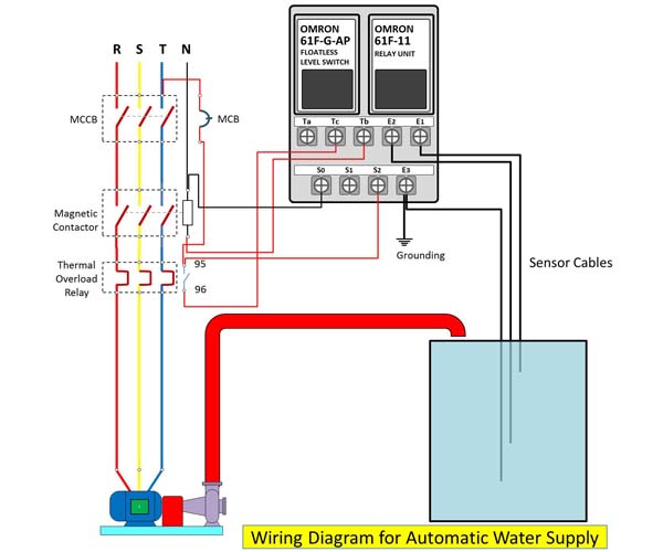
Water level controller circuit description. After connecting all wires, switch on the air switch, then control panel. And this result to both transistors no conduction. Float switch wiring automatic manual single phase water pump controller water pump youtube electrical circuit diagram water level switch water pumps. The water level is sensed by two floats to operate the switches for controlling the pump motor.
This site is an open community for users to do submittion their favorite wallpapers on the internet, all images or pictures in this website are for personal wallpaper use only, it is stricly prohibited to use this wallpaper for commercial purposes, if you are the author and find this image is shared without your permission, please kindly raise a DMCA report to Us.
If you find this site value, please support us by sharing this posts to your favorite social media accounts like Facebook, Instagram and so on or you can also save this blog page with the title automatic water level controller wiring diagram by using Ctrl + D for devices a laptop with a Windows operating system or Command + D for laptops with an Apple operating system. If you use a smartphone, you can also use the drawer menu of the browser you are using. Whether it’s a Windows, Mac, iOS or Android operating system, you will still be able to bookmark this website.

