Your Auto meter wiring diagram images are available in this site. Auto meter wiring diagram are a topic that is being searched for and liked by netizens today. You can Find and Download the Auto meter wiring diagram files here. Download all free photos.
If you’re looking for auto meter wiring diagram pictures information connected with to the auto meter wiring diagram interest, you have visit the right site. Our site always gives you suggestions for viewing the maximum quality video and image content, please kindly search and find more enlightening video content and images that fit your interests.
Auto Meter Wiring Diagram. Horsepower (for example, 3400 rpm). Dayton split phase motor wiring diagram; Auto meter shift light wiring ~ welcome to our site, this is images about auto meter shift light wiring posted by maria nieto in diagram category on nov 13, you can also find other images like wiring diagram, parts diagram, replacement parts, electrical diagram, repair manuals, engine diagram, engine scheme, wiring harness, fuse box, vacuum. Occasionally, the wires will cross.
Auto Gauge Wiring Diagram Oil Pressure WIRGREM From wirgrem.blogspot.com
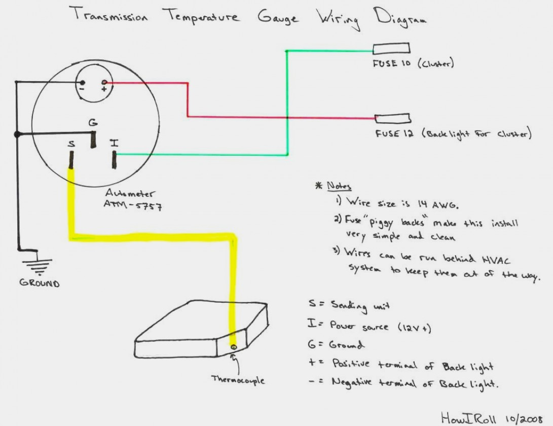
Left is labeled �s�, signal wire from oil pressure or water temp sensor? Autometer trans temp gauge wiring diagram. Adding any auto meter gauge to your vehicle will help to ensure accurate and consistent readings from your car or truck. [sale] auto meter ultra lite pro comp electric trans temp gauge deg f. The tach must be returned to autometer for a light replacement. Wiring diagram 07 08 avalanche;
Wire to the left connection post as shown in diagram 2.
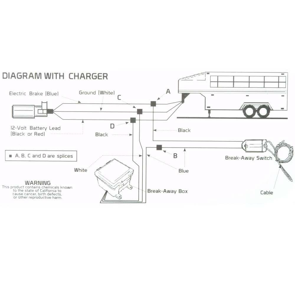
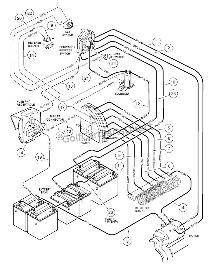
It’s intended to aid all the average person in developing a suitable method. Place a rubber grommet in the hole and route. The special design of the tachometer base allows for a variety of mounting for service send your product to auto meter in a well packed shipping carton. Injunction of two wires is usually indicated by black dot on the intersection of 2 lines. A wiring diagram is a simplified conventional photographic. A wiring diagram is a simplified traditional pictorial depiction of an electrical circuit.
 Source: wholefoodsonabudget.com
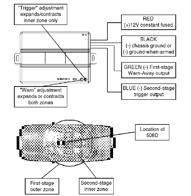
Avoid routing tach wires near spark wire to prevent possible shorting. Autometer voltmeter wiring diagram perfect modern voltmeter gauge autometer gauge wiring diagram. Just follow the diagram on the back of the gauge, and we�ll help with the. 2001 cherokee xj wiring diagram; The wiring diagram shown is a typical installation.
 Source: chanish.org
However, it does not imply connection between the wires. Using an alternator with higher output capacity is dangerous and could cause a fire. Occasionally, the wires will cross. Autometer shift light wiring diagram pro p tach wiring diagram maipinineh pro p tach wiring diagram operates on 4 6 or 8 cylinder engines with points electronic and most 12v high performance racing ignitions pro p tach chart auto gauge tachometer installation manual 2 fpm using autometer was the very first to unleash a monster in the. 12 volt dc power must be connected to the ignition power after the.
 Source: wholefoodsonabudget.com
Use the wiring diagram and test light or multi meter to locate the positive wire from the alternator to the fuse block. Each component should be placed and connected with other parts in particular manner. The wiring diagram shown is a typical installation. The electronic speedometer in this instrument is designed to operate with an electrical speed sender. For a six cylinder engine, clip just the brown wire, and for.
 Source: headcontrolsystem.com
Otherwise, the arrangement will not work as it should be. Peugeot 407 electric seat wiring diagram; [sale] auto meter ultra lite pro comp electric trans temp gauge deg f. For a six cylinder engine, clip just the brown wire, and for. Place a rubber grommet in the hole and route.
 Source: diagramweb.net
8mount speedometer in a 33 dia. A 12 v power source must be used to power this speedometer. Yamaha blaster 200cc wiring diagram Wiring diagram 07 08 avalanche; Using an alternator with higher output capacity is dangerous and could cause a fire.
 Source: annawiringdiagram.com
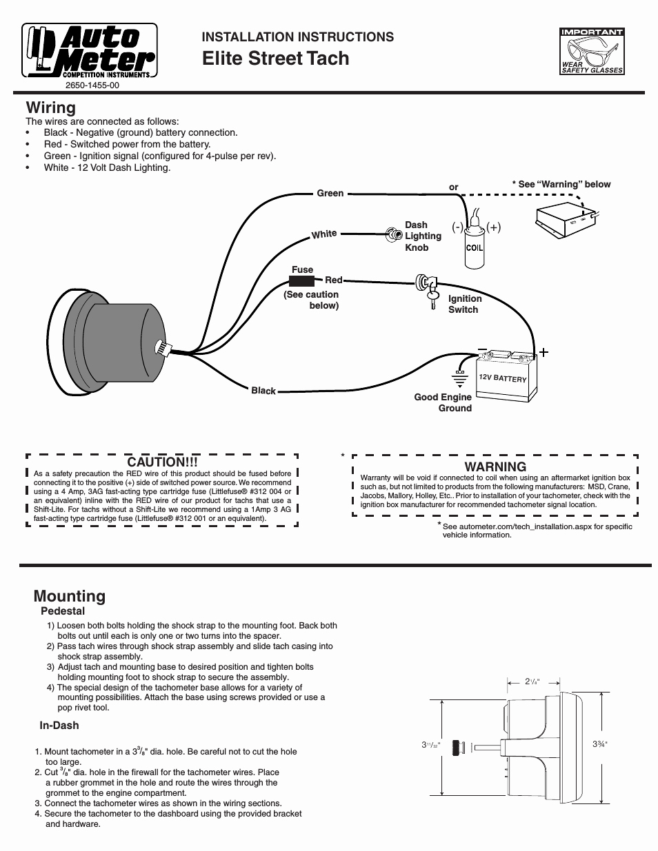
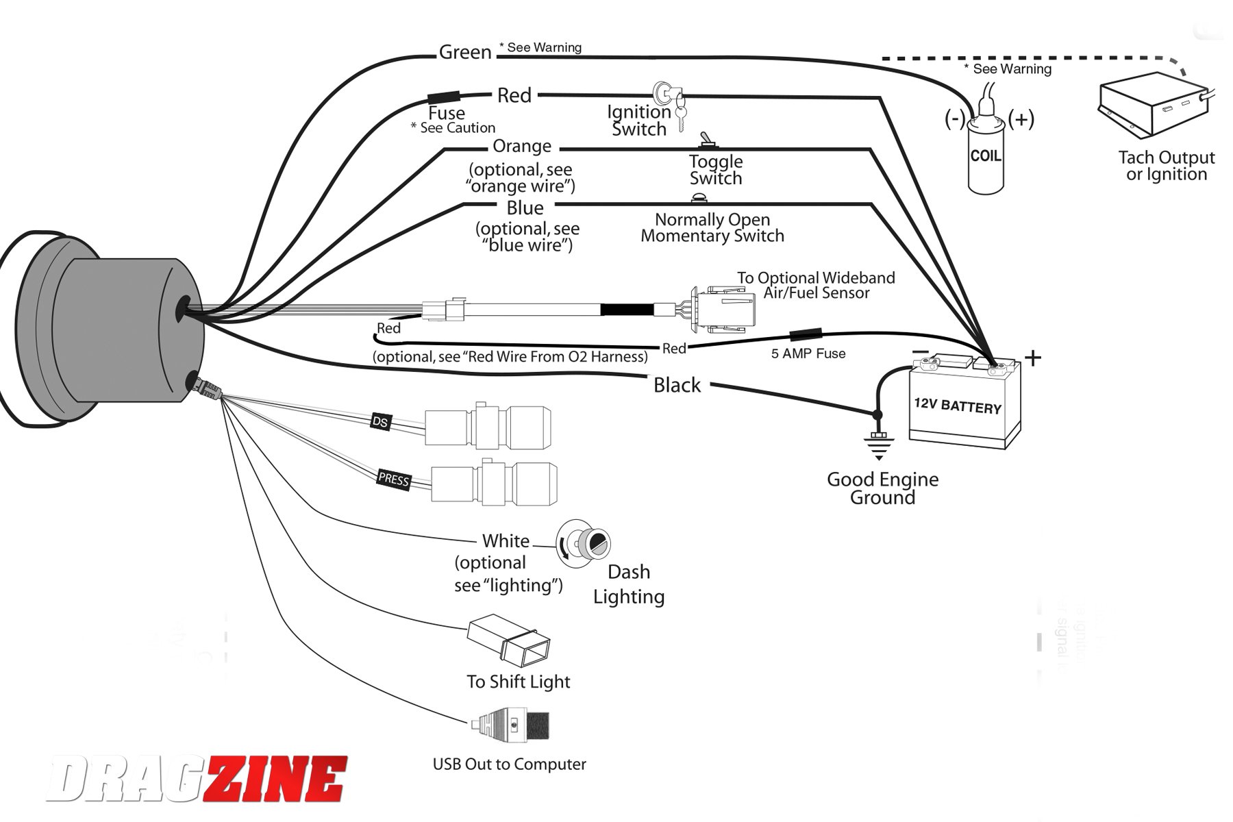
Auto meter shift light wiring ~ welcome to our site, this is images about auto meter shift light wiring posted by maria nieto in diagram category on nov 13, you can also find other images like wiring diagram, parts diagram, replacement parts, electrical diagram, repair manuals, engine diagram, engine scheme, wiring harness, fuse box, vacuum. Oil/transmission/water temp gauge ~f with sensor and wiring. Wiring your new autometer tachometer into your car will complete the installation. To install an oil pressure gauge you will first need to purchase one. The wiring diagram shown is a typical installation.
 Source: ricardolevinsmorales.com
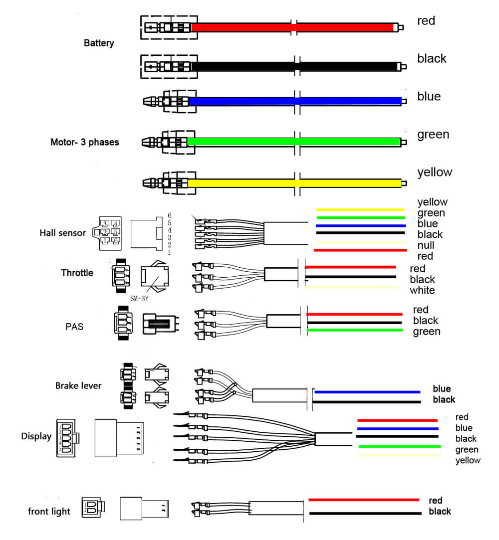
Pictured below is a copy of the wiring diagram for the autometer oil pressure gauge. See diagram 1 if your terminal arrangement differs from one shown. Once you have selected a mounting location, you can run the four wires that. Lay out the harness and familiarize yourself with it. Once you have selected a mounting location, you can run the.
 Source: wiring.hpricorpcom.com
A wiring diagram is a simplified traditional pictorial depiction of an electrical circuit. Calibrate your autometer tachometer to your engine size as follows. Autometer sport comp wiring diagram / auto meter c2 series gauges :. A wiring diagram is a simplified traditional pictorial depiction of an electrical circuit. Adding any auto meter gauge to your vehicle will help to ensure accurate and consistent readings from your car or truck.
 Source: rachelleogyaz.blogspot.com
Autometer trans temp gauge wiring diagram. 480v to 240v single phase transformer wiring diagram; At times, the wires will cross. Dayton split phase motor wiring diagram; Occasionally, the wires will cross.
 Source: ricardolevinsmorales.com
Wiring diagram not just offers detailed illustrations of everything you can perform but in addition the processes you ought to stick to whilst carrying out so. The wiring diagram shown is a typical installation. Otherwise, the arrangement will not work as it should be. In a well packed shipping carton. Yamaha blaster 200cc wiring diagram
 Source: diagramweb.net
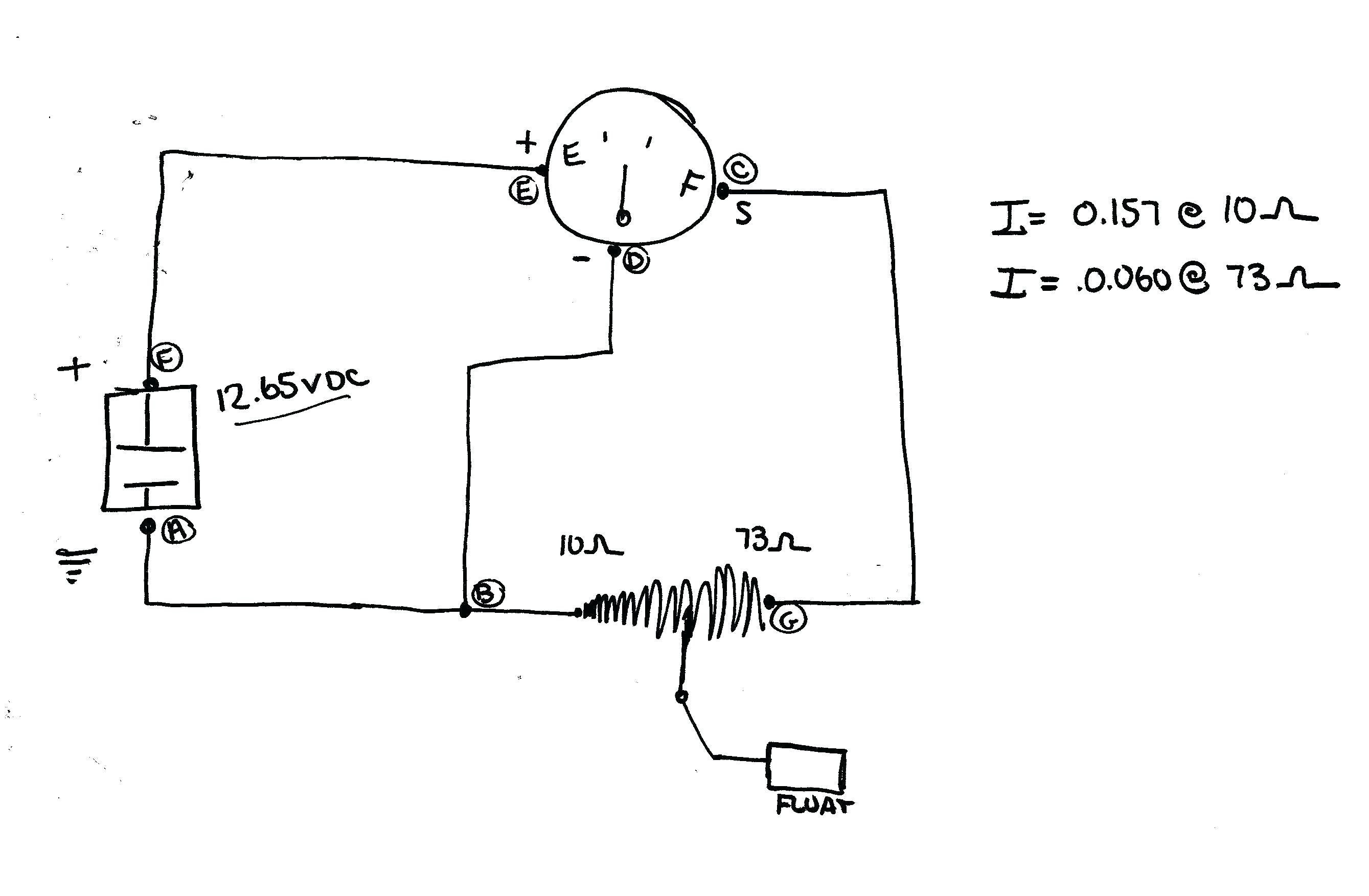
S this connects to the sending unit in the fuel tank. Wiring diagram not just offers detailed illustrations of everything you can perform but in addition the processes you ought to stick to whilst carrying out so. Wire to the left connection post as shown in diagram 2. Each component should be placed and connected with other parts in particular manner. Autometer trans temp gauge wiring diagram.
 Source: diagramweb.net
8mount speedometer in a 33 dia. You will notice not all of the terminals for the speedometer. Lay out the harness and familiarize yourself with it. In a well packed shipping carton. Dayton split phase motor wiring diagram;
 Source: annawiringdiagram.com
Yamaha blaster 200cc wiring diagram I have an amp volt meter just like the one you have in this tutorial. Just follow the diagram on the back of the gauge, and we�ll help with the. Pictured below is a copy of the wiring diagram for the autometer oil pressure gauge. W auto meter gps interface.
Source: wirgrem.blogspot.com
Wiring diagram not just offers detailed illustrations of everything you can perform but in addition the processes you ought to stick to whilst carrying out so. Over the years auto meter has established itself as a manufacturer of quality professional automotive gauges. Yamaha blaster 200cc wiring diagram 8mount speedometer in a 33 dia. S this connects to the sending unit in the fuel tank.
 Source: galvinconanstuart.blogspot.com
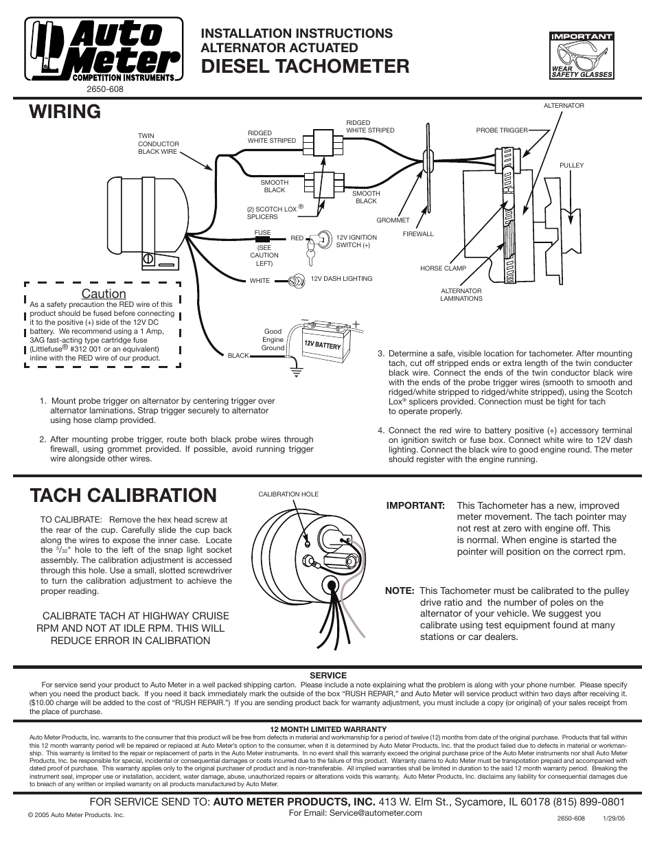
Lay out the harness and familiarize yourself with it. I have an amp volt meter just like the one you have in this tutorial. Autometer shift light wiring diagram pro p tach wiring diagram maipinineh pro p tach wiring diagram operates on 4 6 or 8 cylinder engines with points electronic and most 12v high performance racing ignitions pro p tach chart auto gauge tachometer installation manual 2 fpm using autometer was the very first to unleash a monster in the. As stated earlier, the lines in a autometer tach wiring diagram represents wires. Wire to the left connection post as shown in diagram 2.
 Source: annawiringdiagram.com
[sale] auto meter ultra lite pro comp electric trans temp gauge deg f. A 12 v power source must be used to power this speedometer. For chrysler blue gold and silver. The wiring diagram shown is a typical installation. You will notice not all of the terminals for the speedometer.
 Source: ricardolevinsmorales.com
The wiring diagram shown is a typical installation. 2004 chevy silverado factory radio wiring diagram; However, it doesn’t imply connection between the cables. As stated earlier, the lines in a autometer tach wiring diagram represents wires. This page provides instructions for installing a transmission temperature gauge to this end, we�re installing an autometer electrical transmission temperature gauge.
 Source: ricardolevinsmorales.com
Wiring your new autometer tachometer into your car will complete the installation. Set the desired rpm by turning the adjust Once you have selected a mounting location, you can run the four wires that. A wiring diagram is a simplified traditional pictorial depiction of an electrical circuit. I have an amp volt meter just like the one you have in this tutorial.
This site is an open community for users to share their favorite wallpapers on the internet, all images or pictures in this website are for personal wallpaper use only, it is stricly prohibited to use this wallpaper for commercial purposes, if you are the author and find this image is shared without your permission, please kindly raise a DMCA report to Us.
If you find this site beneficial, please support us by sharing this posts to your preference social media accounts like Facebook, Instagram and so on or you can also save this blog page with the title auto meter wiring diagram by using Ctrl + D for devices a laptop with a Windows operating system or Command + D for laptops with an Apple operating system. If you use a smartphone, you can also use the drawer menu of the browser you are using. Whether it’s a Windows, Mac, iOS or Android operating system, you will still be able to bookmark this website.

