Your Auto gauge rpm wiring diagram images are ready. Auto gauge rpm wiring diagram are a topic that is being searched for and liked by netizens now. You can Find and Download the Auto gauge rpm wiring diagram files here. Get all royalty-free photos and vectors.
If you’re looking for auto gauge rpm wiring diagram images information related to the auto gauge rpm wiring diagram keyword, you have visit the ideal blog. Our website frequently gives you suggestions for viewing the maximum quality video and picture content, please kindly search and find more enlightening video content and graphics that fit your interests.
Auto Gauge Rpm Wiring Diagram. What does an rpm gauge connect to? Otherwise, the structure won’t work as it should be. Unique auto alternator wiring diagram 4 wire inside electrical diagram diagram tachometer. Older dolphin sdometer setup 8 dip switch the 1947 present chevrolet gmc truck message board network.
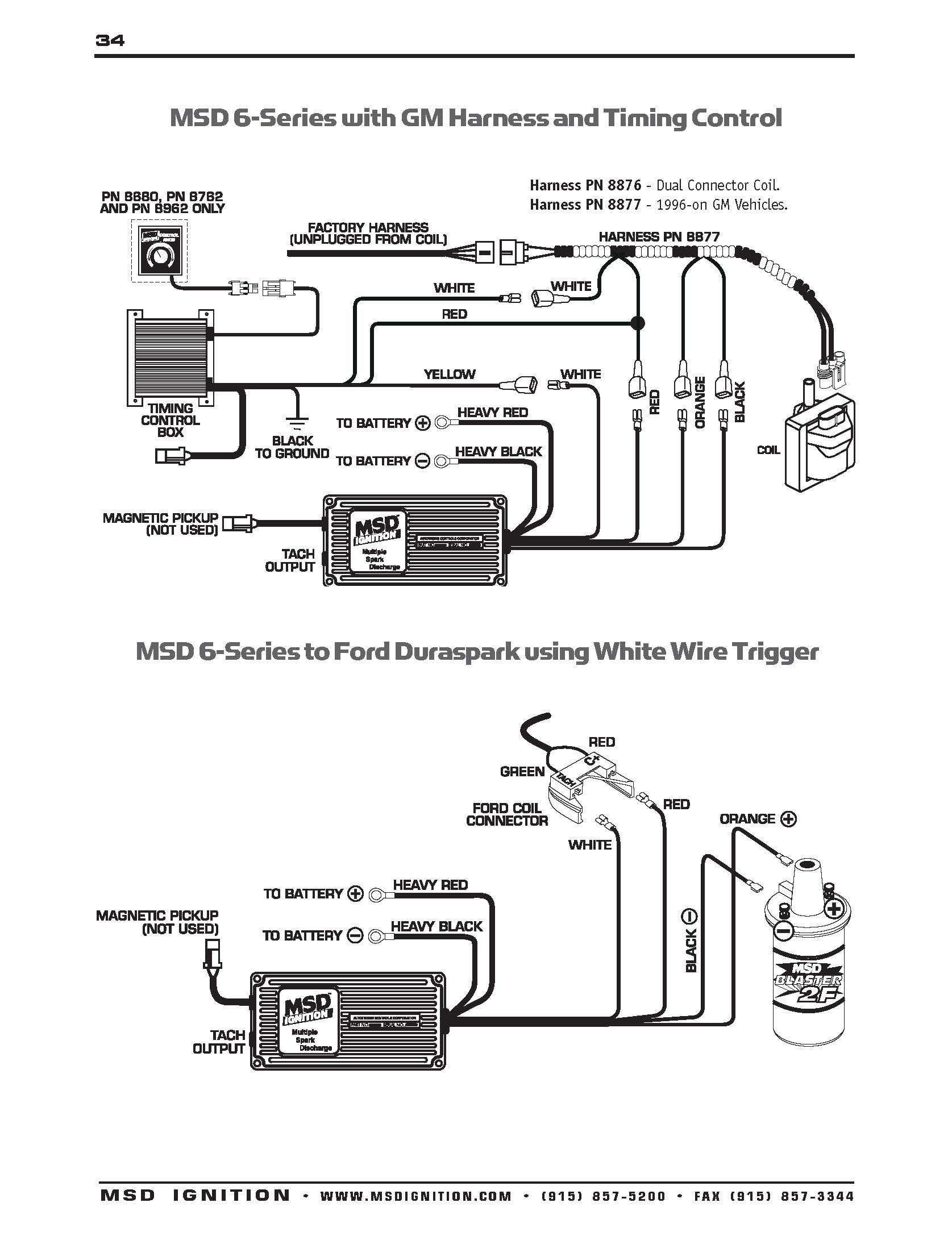
 34 Rpm Gauge Wiring Diagram Wiring Diagram Database From kovodym.blogspot.com
Speed sensor in differential output signal wire is brown/red. How to hook up rpm gauge? Do not install gauges into the passenger side or center of the dashboard. Tachometer wiring diagram with images tachometer automotive. Red tap to rpm wire of your cars rpm gauge. Switch unit (wire 45cm, ft).
Each part should be placed and linked to other parts in specific manner.
Wiring diagram arrives with several easy to follow wiring diagram guidelines. Wiring diagram for a tpi tech sdometer hot rod forum. Also known as an ammeter, this is one of. What does an rpm gauge connect to? Connect the small blue wire and the 10ga blkyel wire into the 2 spots on the female jdm connector as. The wiring diagram shows installation on vehicles with original.
 Source: pinterest.com
This is the circuit diagram of digital tachometer digital rpm meter which can be used for cars or motorcycles with 2 and 4 stroke petrol engines with any number of cylinders and contact. Install an amp gauge in your car and you will instantly know the general condition of your vehicle�s electrical system. When the rpm is above the launch rpm set point: Once you have selected a mounting location, you can run the four wires that. Connect ground wire from ground post on gauge to suitable chassis ground.
 Source: kovodym.blogspot.com
Wiring diagram arrives with several easy to follow wiring diagram guidelines. Are you looking for the best images of rpm gauge drawing? Install an amp gauge in your car and you will instantly know the general condition of your vehicle�s electrical system. On quickcar tach recall wiring diagram. Installing rpm gauge can be easy with this steps.
 Source: wiring88.blogspot.com
Once the unit enters record mode, the launch lite function will no longer be active. Wiring diagram for a tpi tech sdometer hot rod forum. This is the circuit diagram of digital tachometer digital rpm meter which can be used for cars or motorcycles with 2 and 4 stroke petrol engines with any number of cylinders and contact. Tachometer gauge wiring connector fitting instructions 1 1 notes 1 sg3161 (95mm tacho. The tachometer will have wires coming from the back of the gauge.
 Source: mamvic.com
That wire needs to be connected at differential and to the cluster / tachometer input. Install an amp gauge in your car and you will instantly know the general condition of your vehicle�s electrical system. Speed sensor in differential output signal wire is brown/red. I (+) terminal on the back of gauge. Spade on back of gauge.
 Source: headcontrolsystem.com
Wiring diagram ignition harness / fuse box red ignition 12v+ green rpm signal input. Installation instructions for 3 8 programmable sdometer before you start general information signal interface fig 1 wir. Suhner motor dkm 7 wiring diagram; Are you looking for the best images of rpm gauge drawing? Installing rpm gauge can be easy with this steps.
 Source: 2020cadillac.com
Do not install gauges into the passenger side or center of the dashboard. Do not install gauges into the passenger side or center of the dashboard. Ammeter shunted electric speedometer hall effect. Spade on back of gauge. Wiring diagram arrives with several easy to follow wiring diagram guidelines.
 Source: galvinconanstuart.blogspot.com
Once you have selected a mounting location, you can run the four wires that. I (+) terminal on the back of gauge. Tachometer wiring excerpt of 123gt diagram 1800 tach wiring is substantially the same. That wire needs to be connected at differential and to the cluster / tachometer input. Install an amp gauge in your car and you will instantly know the general condition of your vehicle�s electrical system.
 Source: wiringall.com
Wiring your new autometer tachometer into your car will complete the installation. Speed sensor in differential output signal wire is brown/red. Ammeter shunted electric speedometer hall effect. Wiring diagram for a tpi tech sdometer hot rod forum. From model ts to wiring diagrams.
 Source: dannah-mjones.blogspot.com
Electronic sdo sender unit the h a m b. Are you looking for the best images of rpm gauge drawing? The wiring diagram shows installation on vehicles with original. Once you have selected a mounting. The green wire reads the electrical pulses from the ignition.
 Source: annawiringdiagram.com
Suhner motor dkm 7 wiring diagram; Red tap to rpm wire of your cars rpm gauge. Connect ground wire from ground post on gauge to suitable chassis ground. Otherwise, the structure won’t work as it should be. For service send your gauge to auto meter in a well packed shipping carton.
 Source: headcontrolsystem.com
I�m just beginning my journey into the wonderful world of arduino�s, i have an arduino mega 1280, and my goal for it is to use it as the interface between a bus simulator and real gauges and lights on a dashboard i�m building. On quickcar tach recall wiring diagram. Stop when it reaches the desired shift point. Rotate at a very high rate of speed. On defi rpm gauge wiring diagram.
 Source: rollaclub.com
The tachometer will have wires coming from the back of the gauge. Wiring diagram for autometer gauges. I (+) terminal on the back of gauge. Apexi rsm rev speed meter round button manual russian: Wiring diagram ignition harness / fuse box red ignition 12v+ green rpm signal input.
 Source: wiring88.blogspot.com
How to hook up rpm gauge? Wiring diagram ignition harness / fuse box red ignition 12v+ green rpm signal input. Connection diagram vehicle harness red wire: The green wire reads the electrical pulses from the ignition. Wiring diagram for autometer gauges.
 Source: shs99reunion.blogspot.com
This is the circuit diagram of digital tachometer digital rpm meter which can be used for cars or motorcycles with 2 and 4 stroke petrol engines with any number of cylinders and contact. Horsepower (for example, 3400 rpm). Negative side of ignition coil or ecu tach wire saas automotive pty ltd 25 metrolink circuit west campbellfield victoria 3061 australia abn: This tachometer has an air. Connect wire from ignition switch to the positive.
 Source: schematron.org
On quickcar tach recall wiring diagram. Connection diagram vehicle harness red wire: Autometer pro comp ultra lite wiring diagram fresh auto meter wiring autometer gauge wiring diagram. The tachometer will have wires coming from the back of the gauge. The green wire reads the electrical pulses from the ignition.
![[DIAGRAM] Auto Meter 9117 Tachometer Adapter Installation](https://static-cdn.imageservice.cloud/4235701/type-r-gauge-wire-diagram-everything-wiring-diagram.jpg "[DIAGRAM] Auto Meter 9117 Tachometer Adapter Installation") Source: curcuitdiagrams.jokergiochi.it
Source: curcuitdiagrams.jokergiochi.it
Stewart warner amp gauge wiring diagram wiring diagram is a simplified adequate pictorial representation of an electrical circuit. This tachometer has an air. It’s intended to aid all the average person in developing a suitable method. Installing rpm gauge can be easy with this steps. Once the unit enters record mode, the launch lite function will no longer be active.
 Source: dentistmitcham.com
Switch unit (wire 45cm, ft). Tachometer wiring excerpt of 123gt diagram 1800 tach wiring is substantially the same. Tachometers with two or three buttons use an advanced microcontroller circuit to measure engine rpm for increased accuracy and zero pointer flutter at low rpm. Connection diagram vehicle harness red wire: Rotate at a very high rate of speed.
 Source: clipartmag.com
Electronic sdo sender unit the h a m b. Electronic sdo sender unit the h a m b. Once the unit enters record mode, the launch lite function will no longer be active. Connection diagram vehicle harness red wire: From model ts to wiring diagrams.
This site is an open community for users to do sharing their favorite wallpapers on the internet, all images or pictures in this website are for personal wallpaper use only, it is stricly prohibited to use this wallpaper for commercial purposes, if you are the author and find this image is shared without your permission, please kindly raise a DMCA report to Us.
If you find this site value, please support us by sharing this posts to your favorite social media accounts like Facebook, Instagram and so on or you can also bookmark this blog page with the title auto gauge rpm wiring diagram by using Ctrl + D for devices a laptop with a Windows operating system or Command + D for laptops with an Apple operating system. If you use a smartphone, you can also use the drawer menu of the browser you are using. Whether it’s a Windows, Mac, iOS or Android operating system, you will still be able to bookmark this website.