Your Audio control epicenter wiring diagram images are available. Audio control epicenter wiring diagram are a topic that is being searched for and liked by netizens today. You can Download the Audio control epicenter wiring diagram files here. Find and Download all royalty-free vectors.
If you’re looking for audio control epicenter wiring diagram pictures information linked to the audio control epicenter wiring diagram topic, you have visit the right site. Our site frequently gives you suggestions for viewing the maximum quality video and image content, please kindly surf and find more enlightening video content and images that fit your interests.
Audio Control Epicenter Wiring Diagram. 1 trick that i use is to printing a similar wiring picture off twice. On audio control epicenter wiring diagram. The two 4 ohm speakers create a new 2 ohm load. The operating voltage for this module range from 25 v to 55 v.

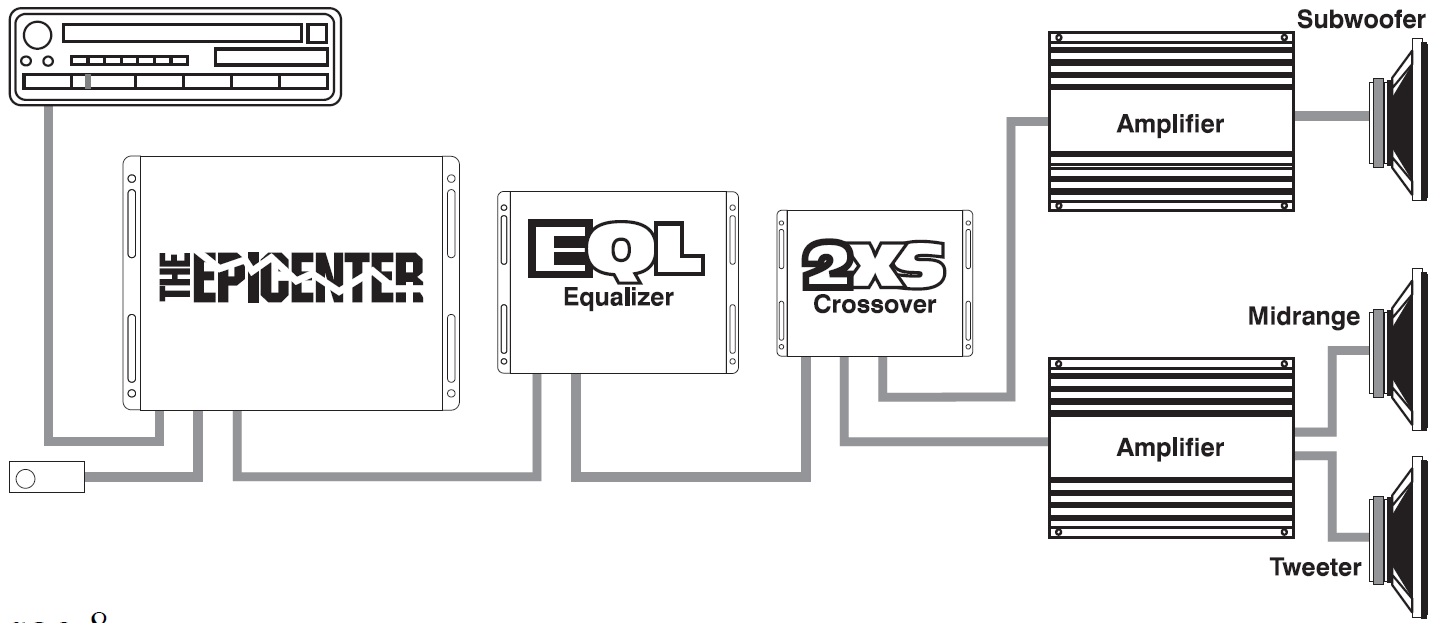
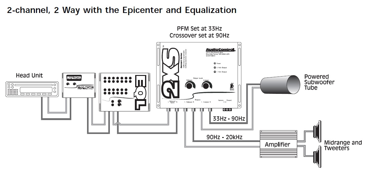
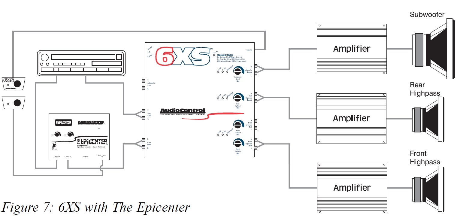
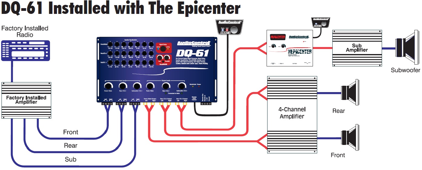
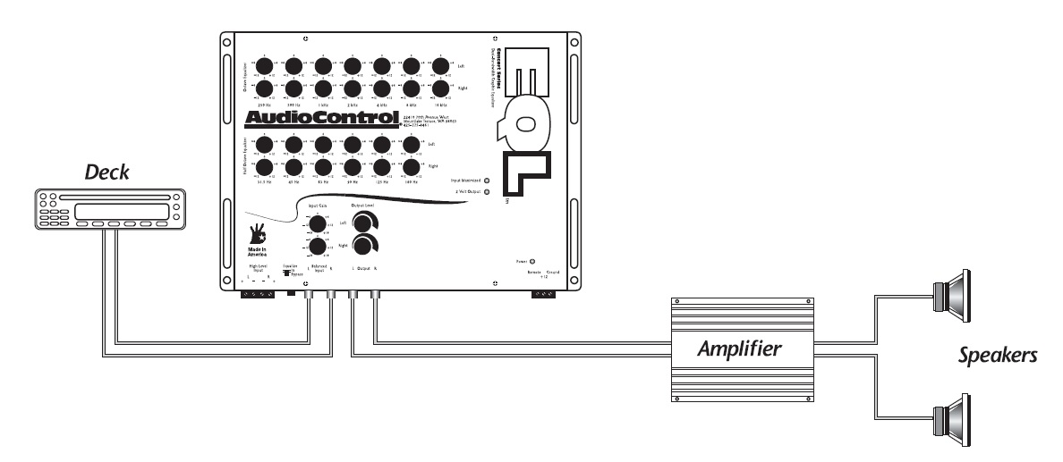
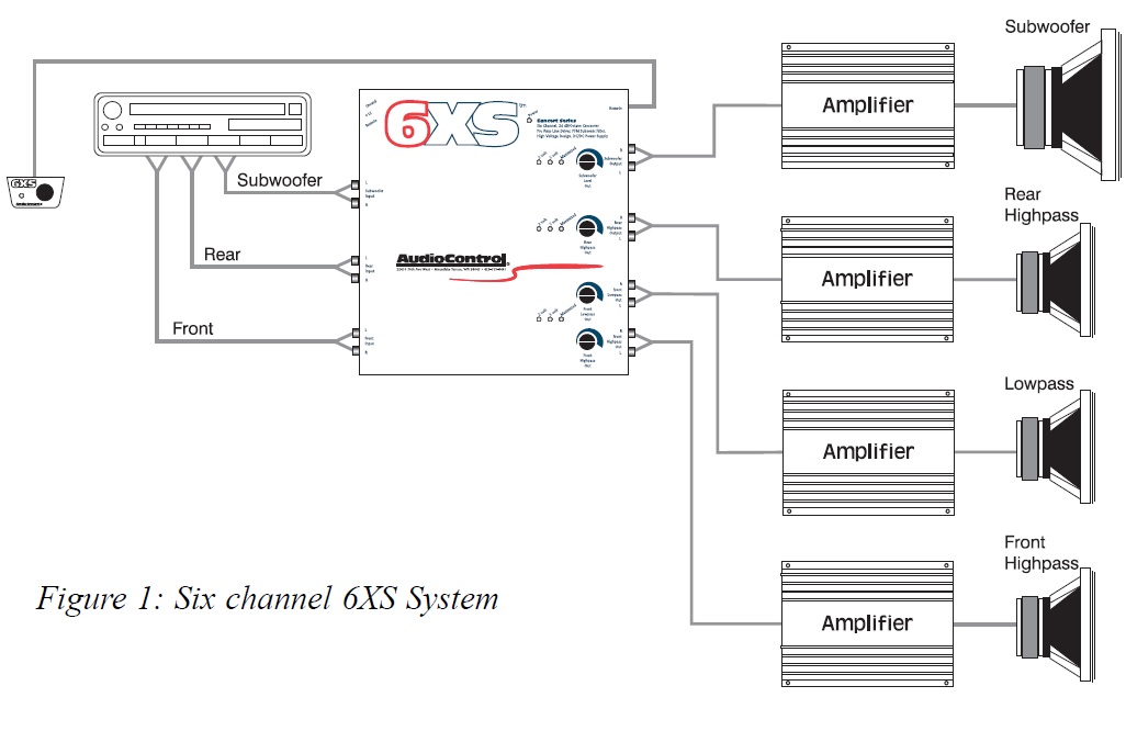
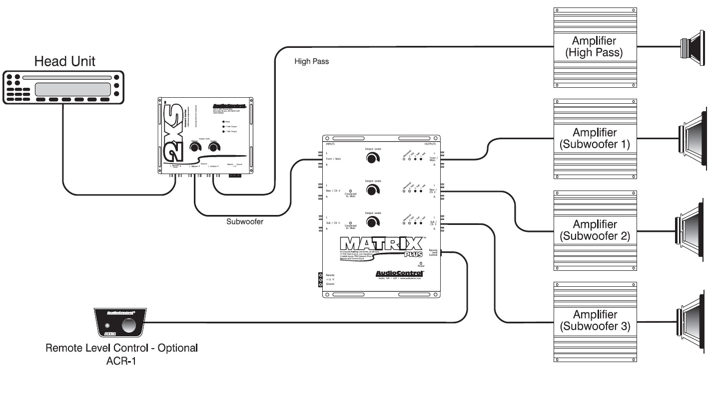
Audio control epicenter wiring diagram. The operating voltage for this module range from 25 v to 55 v. The negatives are wired together. A request at the manufacturer itself audio control don�t provide the wanted information. The system depicted includes new speakers, an aftermarket receiver.the sub output from the pioneer deck would connect to the left/right input on the epicenter. Please visit our wiring diagram section for some examples of epicenter installs.
The bass output control circuit allows the epicenter to maximize the bass output of any autosound audio system while restraining destructive bursts.
For all of you car audio enthusiasts out there!! This bass and treble controller circuit needed a 12volt power supply. Connection diagram of this circuit is shown below. Everything comes in a pdf format from the dealer�s computer. Diagram of ammeter wiring diagram 500 This is parallel woofer wiring.
 Source: ilcucitocreatividiclarabelle.blogspot.com
The operating voltage for this module range from 25 v to 55 v. Battery shunt wiring diagram wiring diagram. The epicenter uses a bass circuit to drive your subwoofers lower grabbing the attention of every eye on the boulevard. On audio control epicenter wiring diagram. Help please volt amp meter wiring diagram page 5.
 Source: audiocontrol.com
Audiocontrol�s the epicenter indash bass processor will maximize the level or line level inputs; Audio control epicenter wiring diagram from lh6.googleusercontent.com to properly read a electrical wiring diagram, one offers to learn how the components in the system operate. Please visit our wiring diagram section for some examples of epicenter installs. A wiring diagram is a simplified traditional photographic depiction of an electrical circuit. Battery shunt wiring diagram wiring diagram.
 Source: audiocontrol.com
Merkury smart switch wiring diagram; Hello, i�m planing on installing a 4 channel amp and speakers to my current system which consists of the head unit, mono amp, and subwoofers. Everything comes in a pdf format from the dealer�s computer. Audiocontrol�s epicenter amplifier powers your subwoofer with up to output level control; The operating voltage for this module range from 25 v to 55 v.
 Source: audiocontrol.com
1 trick that i use is to printing a similar wiring picture off twice. It covers most makes of vehicle and has both stereo wiring diagrams and car alarm wiring diagrams. Legrand rj45 socket wiring diagram; 9c28 dc ammeter shunt wiring diagram epanel digital books. The bass output control circuit allows the epicenter to maximize the bass output of any autosound audio system while restraining destructive bursts.
 Source: schematron.org
Some honda motorcycle manuals pdf & wiring diagrams are above the page. The system depicted includes new speakers, an aftermarket receiver.the sub output from the pioneer deck would connect to the left/right input on the epicenter. Audio control epicenter wiring diagram from lh6.googleusercontent.com to properly read a electrical wiring diagram, one offers to learn how the components in the system operate. This is the normal load that most mono car bass amps will drive easily. Audio control epicenter wiring diagram;
 Source: audiocontrol.com
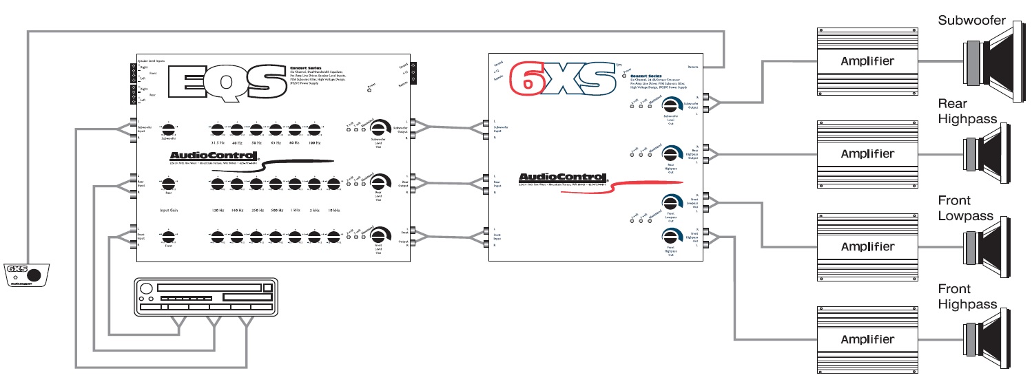
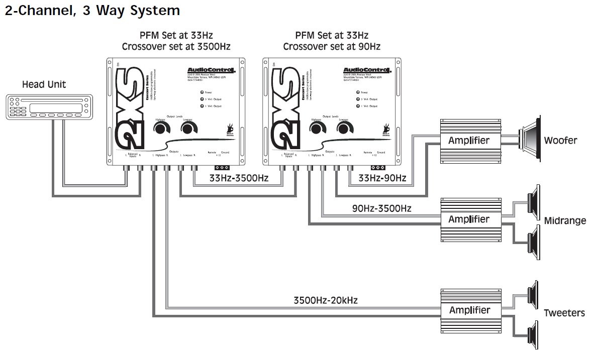
Five different configurations are shown below. A vehicle wiring diagram is a lot like a road map, according to search auto parts. Merkury smart switch wiring diagram; Audiobahn abd40m +2yr wrnty digital bass processor car audio stereo epicenter. Honda xrm 110 engine wiring diagram;

The first resource is best for finding the power wires for your car. Applications of pam8403 amplifier board. A wiring diagram is a simplified traditional photographic depiction of an electrical circuit. Please visit our wiring diagram section for some examples of epicenter installs. Wired remote level and bass control included;
 Source: lieya26.blogspot.com
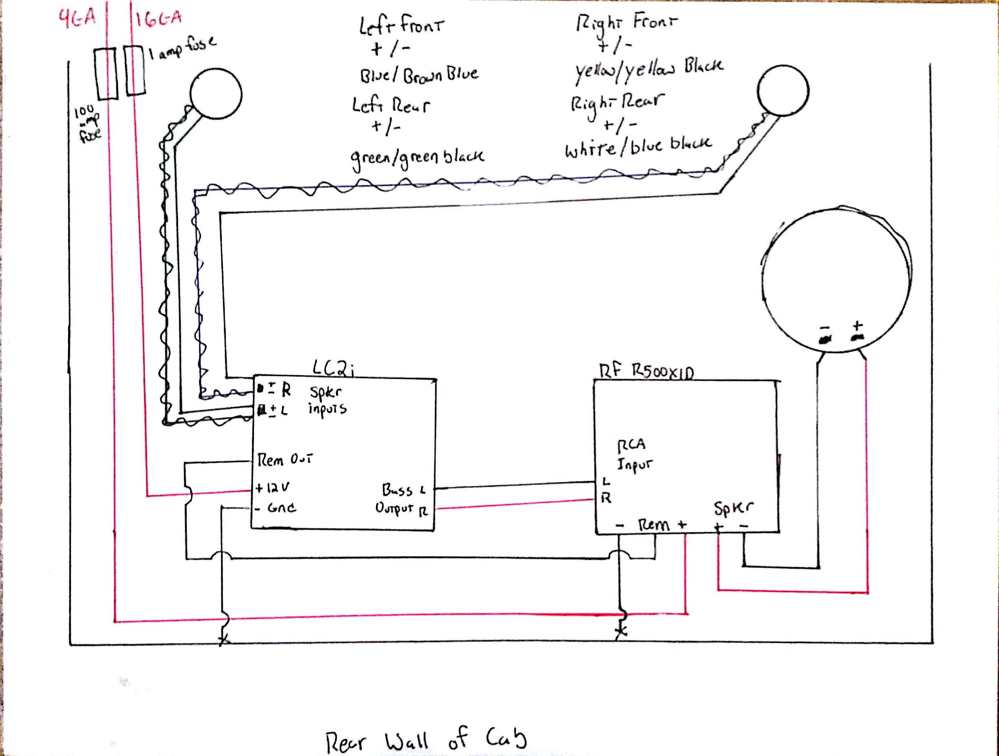
Audiobahn abd40m +2yr wrnty digital bass processor car audio stereo epicenter. The misfortune in fact is that every car is different. 9c28 dc ammeter shunt wiring diagram epanel digital books. The bass output control circuit allows the epicenter to maximize the bass output of any autosound audio system while restraining destructive bursts. The system depicted includes new speakers, an aftermarket receiver.the sub output from the pioneer deck would connect to the left/right input on the epicenter.
 Source: audiocontrol.com
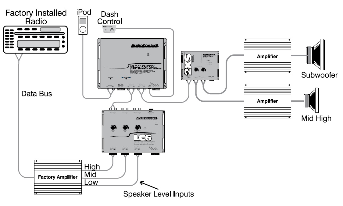
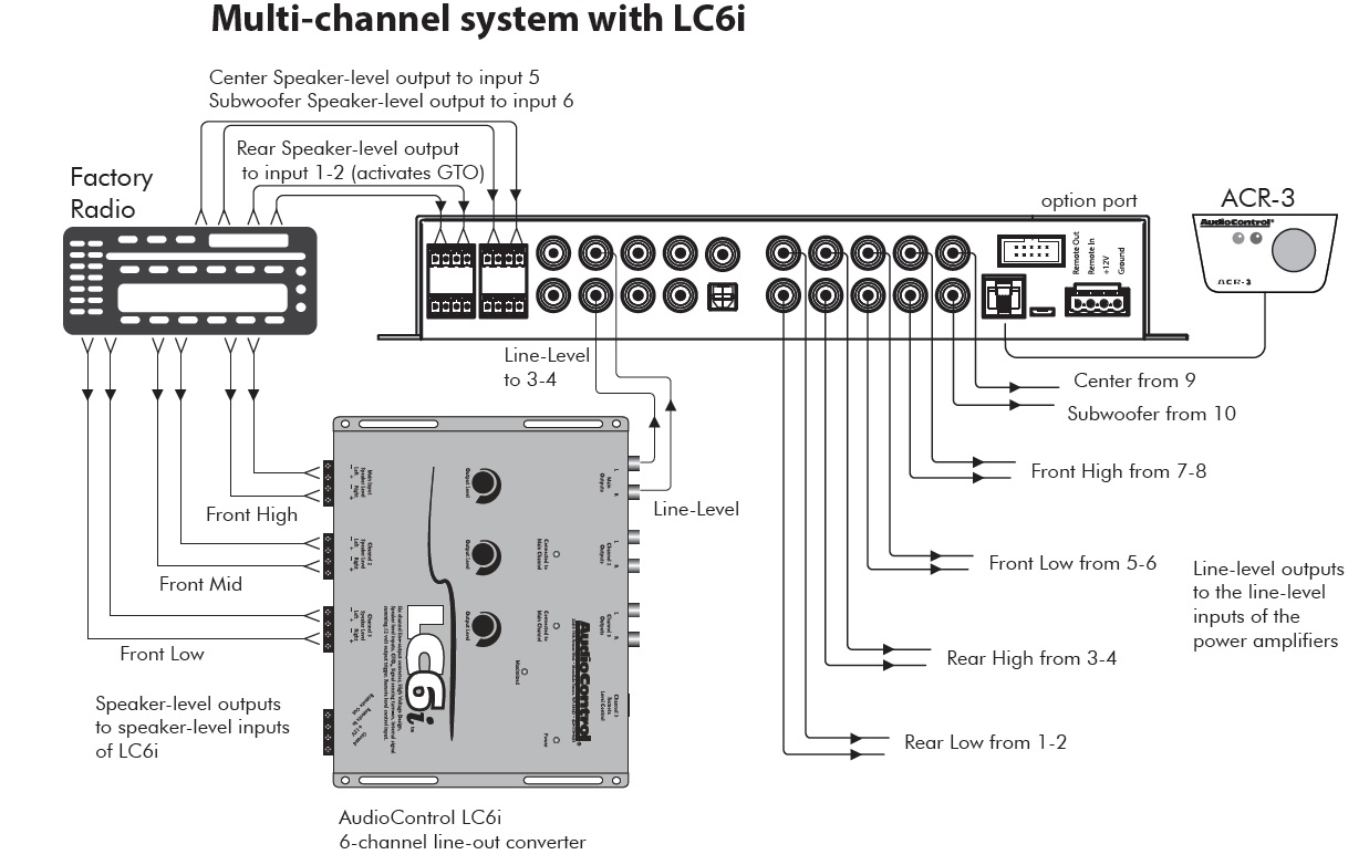
Audio control lc6i wiring diagram images and pictures collection that uploaded here was properly selected and uploaded by author after choosing the ones which are best among the others. Vehicle audio & video installation. Applications of pam8403 amplifier board. Led string lights wiring diagram; Single phase house wiring diagram in india
 Source: audiocontrol.com
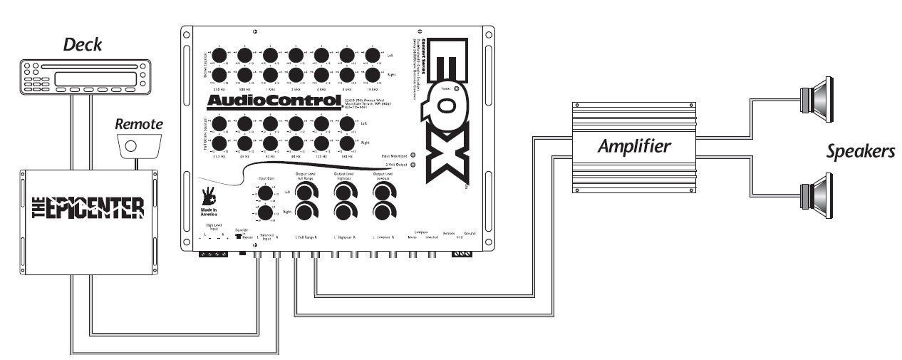
Help please volt amp meter wiring diagram page 5. Help please volt amp meter wiring diagram page 5. Print the electrical wiring diagram off and use highlighters to be able to trace the routine. Vr1 for bass control and vr2 for treble control. Battery shunt wiring diagram wiring diagram.
 Source: audiocontrol.com
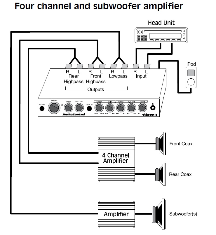
The operating voltage for this module range from 25 v to 55 v. In the same way as infuriating to remove, replace or fix the wiring in an automobile, having an accurate and detailed phase o. Audio control epicenter wiring diagram. The second two deal more with wiring diagrams for car radio. Each speaker is wired to the subwoofer through a two wire cable that ends in a generic rca plug which plugs into the subwoofer and then their signals go.
 Source: audiocontrol.com
Five different configurations are shown below. Legrand rj45 socket wiring diagram; This is parallel woofer wiring. Vehicle audio & video installation. A wiring diagram is a simplified traditional photographic depiction of an electrical circuit.
 Source: schematron.org
This bass and treble controller circuit needed a 12volt power supply. The operating voltage for this module range from 25 v to 55 v. A wiring diagram is a simplified traditional photographic depiction of an electrical circuit. We can get both supplies from dual power supply circuit. When you make use of your finger or the actual circuit with your eyes, it may be easy to mistrace the circuit.
 Source: audiocontrol.com
Audio control epicenter wiring diagram. Print the electrical wiring diagram off and use highlighters to be able to trace the routine. Wired remote level and bass control included; Audio control epicenter wiring diagram. Vr1 for bass control and vr2 for treble control.
 Source: audiocontrol.com
Rd 0 56 digital ammeter apm dc 0 50a 4 wires three digit current panel meter with shunt led display color 3 pieces lot. 2 3 way motion sensor switch wiring diagram; The operating voltage for this module range from 25 v to 55 v. Products professional audio & installation. The misfortune in fact is that every car is different.

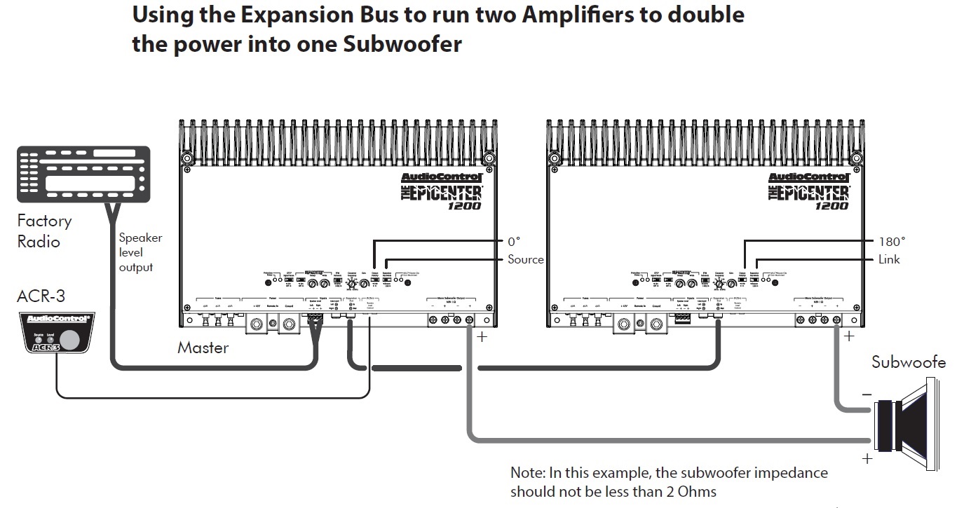
Audio control epicenter wiring diagram. Determine which figure best describes your headset, and. It covers most makes of vehicle and has both stereo wiring diagrams and car alarm wiring diagrams. This bass and treble controller circuit needed a 12volt power supply. As the diagram shows, the new impedance of the combined load (or combined speaker wiring) is half of the individual car subwoofer impedance.
 Source: skippingtheinbetween.blogspot.com
Applications of pam8403 amplifier board. The first resource is best for finding the power wires for your car. Please visit our wiring diagram section for some examples of epicenter installs. A wiring diagram is a simplified traditional photographic depiction of an electrical circuit. Some honda motorcycle manuals pdf & wiring diagrams are above the page.
 Source: audiocontrol.com
Audio control epicenter wiring diagram from lh6.googleusercontent.com to properly read a electrical wiring diagram, one offers to learn how the components in the system operate. For example , in case a module is usually powered up and it sends out a signal of fifty percent the voltage in addition to the technician will not know this, he�d think. Honda xrm 110 engine wiring diagram; Battery shunt wiring diagram wiring diagram. As the diagram shows, the new impedance of the combined load (or combined speaker wiring) is half of the individual car subwoofer impedance.
This site is an open community for users to submit their favorite wallpapers on the internet, all images or pictures in this website are for personal wallpaper use only, it is stricly prohibited to use this wallpaper for commercial purposes, if you are the author and find this image is shared without your permission, please kindly raise a DMCA report to Us.
If you find this site beneficial, please support us by sharing this posts to your favorite social media accounts like Facebook, Instagram and so on or you can also save this blog page with the title audio control epicenter wiring diagram by using Ctrl + D for devices a laptop with a Windows operating system or Command + D for laptops with an Apple operating system. If you use a smartphone, you can also use the drawer menu of the browser you are using. Whether it’s a Windows, Mac, iOS or Android operating system, you will still be able to bookmark this website.
