Your Alliance tenna rotor wiring diagram images are ready in this website. Alliance tenna rotor wiring diagram are a topic that is being searched for and liked by netizens today. You can Get the Alliance tenna rotor wiring diagram files here. Download all royalty-free images.
If you’re searching for alliance tenna rotor wiring diagram pictures information connected with to the alliance tenna rotor wiring diagram interest, you have come to the right site. Our website frequently gives you hints for refferencing the highest quality video and image content, please kindly hunt and locate more enlightening video content and graphics that fit your interests.
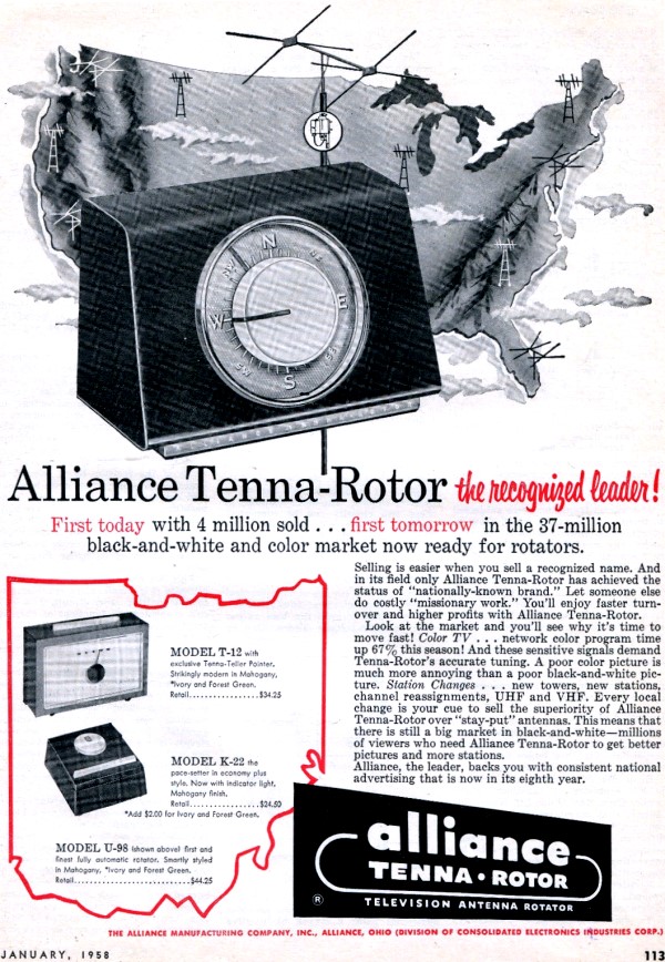
Alliance Tenna Rotor Wiring Diagram. Control and feedback is about as simple as it gets with a motor turning the antenna mast and a solenoid in the control box that. Shipping weight — 17 lbs. (mechanically) when rotation is complete. Alliance is out of the rotor business completely.

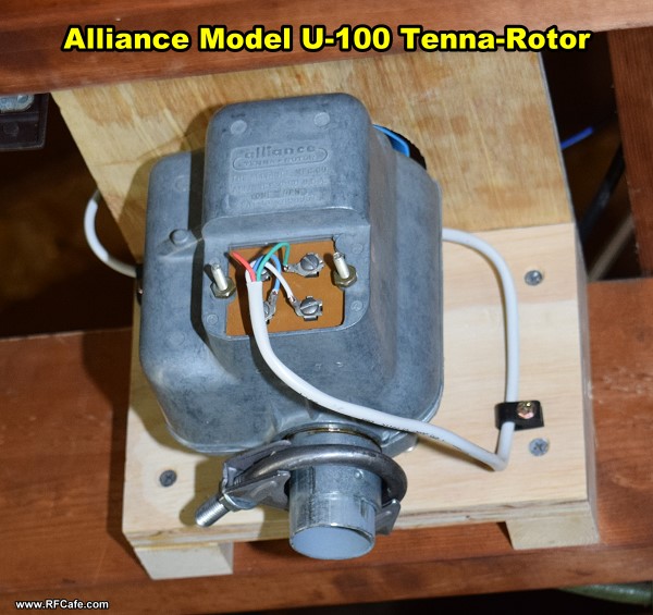
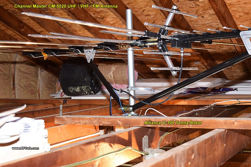
Source of data collector info sammler. Antenna rotor wiring diagram wiring diagram line wiring diagram. (mechanically) when rotation is complete. Yaesu g 400 antenna rotator controller under repository circuits 49394 next gr digiwave ar 500 plus programmable vintage alliance model u 100 tenna rotor installation kirt s cogitation 301 rf cafe two control circuit diagram seekic com interfacing a microcontroller arduino to cde qrz forums system quick guide for. The unit operates at a speed of one 1. It belonged to my grandfather years ago before i moved in.
Control and feedback is about as simple as it gets with a motor turning the antenna mast and a solenoid in the control box that advances the dial as the antenna rotates.
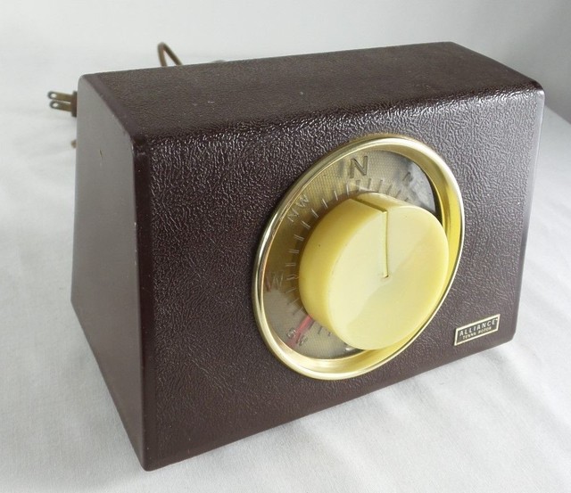
The dial of the control box lights when the. I do not have the controller but i do remember the controller he had was the one with the n e s w n lettering on the face and the long white button on the top of the unit. Source of data collector info sammler. I guess it dried up and cracked. By floyd sens » thu, 03 feb 2005 22:15:13. Control and feedback is about as simple as it gets with a motor turning the antenna mast and a solenoid in the control box that advances the dial as the antenna rotates.
 Source: easywiring.info
Modern plastics no bakelite or catalin shape. Motor voltage — 20 volts a.c. Cams on both ends open and close contacts as required. Modern plastics no bakelite or catalin shape. Wiring diagram the 3.005.190 a.
 Source: rfcafe.com
The alliance tenna rotor u is a fully automatic unit. My rotor has 3 only wiring terminals, and it. Cams on both ends open and close contacts as required. (mechanically) when rotation is complete. I guess it dried up and cracked.
 Source: ebay.com
Alliance tenna rotor wiring diagram. Alliance laundry systems is not responsible for personal injury or property damage resulting from improper service. Cams on both ends open and close contacts as required. The unit operates at a speed of one 1. For proper performance do not exceed the maximum lengths.
 Source: youtube.com
Dimensions (whd) 6.5 x 4.75 x 3.75 inch / 165 x 121 x 95 mm. Motor — capacitor split phase, reversible. No voltage on motor or leads exceeds u.l. Antenna rotor wiring diagram wiring diagram line wiring diagram. Source of data collector info sammler.
 Source: rfcafe.com
It changes for the no. The good news is that norm�s rotor service has bought all parts, all materials, and all technical data from alliance. When you move the knob on the. Shipping weight — 17 lbs. Need to build control box for alliance tenna rotor.
![[Download 29+] Channel Master Tv Antenna Rotor Wiring Diagram [Download 29+] Channel Master Tv Antenna Rotor Wiring Diagram](https://static-assets.imageservice.cloud/17204025/channel-master-wiring-diagram-wiring-diagram-database.png) Source: grealish-2374.blogspot.com
Source: grealish-2374.blogspot.com
The theory of operation concerns two separate circuits. Need to build control box for alliance tenna rotor. The alliance tenna rotor u is a fully automatic unit. It changes for the no. Antenna rotor wiring diagram wiring diagram line wiring diagram.
![[BV_0109] Antenna Rotor Wiring Diagram Wiring Diagram [BV_0109] Antenna Rotor Wiring Diagram Wiring Diagram](https://static-resources.imageservice.cloud/4387454/wrg-3749-antenna-rotor-wiring-diagram.jpg) Source: osoph.syny.pap.mohammedshrine.org
Source: osoph.syny.pap.mohammedshrine.org
It just slips over the upper pipe piece, (externally on top of rotor) and is tapered to shed water. G 400 antenna rotator controller under repository circuits 49394 next gr digiwave ar 500 plus programmable vintage alliance model u 100 tenna rotor installation kirt s cogitation 301 rf cafe two control circuit diagram seekic com interfacing a microcontroller arduino to cde. 5 thoughts on alliance hd73 wiring diagram. The rotor case is almost the same for all the models: By floyd sens » thu, 03 feb 2005 22:15:13.
 Source: easywiring.info
And a pinpoint slower speed. Modern plastics no bakelite or catalin shape. Vintage original alliance tenna rotor paper wire diagram channel master anteena. The alliance tenna rotor u is a fully automatic unit. It changes for the no.
 Source: rfcafe.com
Control and feedback is about as simple as it gets with a motor turning the antenna mast and a solenoid in the control box that advances the dial as the antenna rotates. Antenna rotor wiring diagram wiring diagram line wiring diagram. 5 thoughts on alliance hd73 wiring diagram. Alliance tenna rotor wiring diagram. Step 4 slide terminal cover up cable and fasten over terminals as shown.
 Source: eunetcom.eu
Step 6 clamp rotor on mast step attach set screw and nut t o clamp plate. Step 6 clamp rotor on mast step attach set screw and nut t o clamp plate. A wiring diagram is a simplified traditional photographic depiction of an electrical circuit. Cams on both ends open and close contacts as required. I do not have the controller but i do remember the controller he had was the one with the n e s w n lettering on the face and the long white button on the top of the unit.

I guess it dried up and cracked. Yaesu g 400 antenna rotator controller under repository circuits 49394 next gr digiwave ar 500 plus programmable vintage alliance model u 100 tenna rotor installation kirt s cogitation 301 rf cafe two control circuit diagram seekic com interfacing a microcontroller arduino to cde qrz forums system quick guide for. And a pinpoint slower speed. How to wire solar panel to 220 v inverter 12v battery 12v dc load and 220v ac load 220v fan light etc ac dc load. I found it on the ground under the antenna, in 2 pieces.
![[Download 29+] Channel Master Tv Antenna Rotor Wiring Diagram [Download 29+] Channel Master Tv Antenna Rotor Wiring Diagram](https://www.rfcafe.com/miscellany/factoids/images/Alliance-Tenna-Rotor-U-100-f.jpg) Source: grealish-2374.blogspot.com
Source: grealish-2374.blogspot.com
The unit operates at a speed of one (1. Alliance tenna rotor wiring diagram. Source of data collector info sammler. I do not have the controller but i do remember the controller he had was the one with the n e s w n lettering on the face and the long white button on the top of the unit. It changes for the no.
 Source: pinterest.com
It just slips over the upper pipe piece, (externally on top of rotor) and is tapered to shed water. Step 6 clamp rotor on mast step attach set screw and nut t o clamp plate. Controller, one part of the dial is under spring tension and a solenoid that. My rotor has 3 only wiring terminals, and it. I found it on the ground under the antenna, in 2 pieces.
![[BV_0109] Antenna Rotor Wiring Diagram Wiring Diagram [BV_0109] Antenna Rotor Wiring Diagram Wiring Diagram](https://static-cdn.imageservice.cloud/6196543/cdr-rotor-control-wiring-diagram-wiring-diagram-schematics.jpg) Source: osoph.syny.pap.mohammedshrine.org
Source: osoph.syny.pap.mohammedshrine.org
(mechanically) when rotation is complete. Cams on both ends open and close contacts as required. A wiring diagram is a simplified traditional photographic depiction of an electrical circuit. Wiring diagram the 3.005.190 a. For proper performance do not exceed the maximum lengths.
 Source: easywiring.info
For proper performance do not exceed the maximum lengths. Tenna rotor t 10 antenna pdf manual download. It just slips over the upper pipe piece, (externally on top of rotor) and is tapered to shed water. My rotor has 3 only wiring terminals, and it. Has anyone got the wiring diagram for a alliance tenna rotater 4 wire from box to rotator, thanks.
 Source: wiringdiagram.2bitboer.com
The unit operates at a speed of one 1. I do not have the controller but i do remember the controller he had was the one with the n e s w n lettering on the face and the long white button on the top of the unit. I found it on the ground under the antenna, in 2 pieces. Modern plastics no bakelite or catalin shape. The theory of operation concerns two separate circuits.
 Source: wiringdiagram.2bitboer.com
Alliance is out of the rotor business completely. Rotator speed — dual — 1 r.p.m. 5 thoughts on alliance hd73 wiring diagram. Step 6 clamp rotor on mast step attach set screw and nut t o clamp plate. Tenna rotor t 10 antenna pdf manual download.
 Source: lost-manuals.com
Rotator speed — dual — 1 r.p.m. I found it on the ground under the antenna, in 2 pieces. It just slips over the upper pipe piece, (externally on top of rotor) and is tapered to shed water. Source of data collector info sammler. And a pinpoint slower speed.
This site is an open community for users to do sharing their favorite wallpapers on the internet, all images or pictures in this website are for personal wallpaper use only, it is stricly prohibited to use this wallpaper for commercial purposes, if you are the author and find this image is shared without your permission, please kindly raise a DMCA report to Us.
If you find this site value, please support us by sharing this posts to your preference social media accounts like Facebook, Instagram and so on or you can also bookmark this blog page with the title alliance tenna rotor wiring diagram by using Ctrl + D for devices a laptop with a Windows operating system or Command + D for laptops with an Apple operating system. If you use a smartphone, you can also use the drawer menu of the browser you are using. Whether it’s a Windows, Mac, iOS or Android operating system, you will still be able to bookmark this website.
