Your Airmar transducer wiring diagram images are ready. Airmar transducer wiring diagram are a topic that is being searched for and liked by netizens now. You can Get the Airmar transducer wiring diagram files here. Find and Download all royalty-free photos.
If you’re looking for airmar transducer wiring diagram pictures information linked to the airmar transducer wiring diagram keyword, you have come to the ideal blog. Our website frequently provides you with suggestions for seeing the maximum quality video and picture content, please kindly surf and find more enlightening video content and graphics that fit your interests.
Airmar Transducer Wiring Diagram. If the installed transducer has more than the three wires indicated in the wiring For wooden or frp vessel using a steel tank, attach a zinc plate to the hull to prevent electrolytic corrosion. **the blue/white wire will be a yellow wire if manufactured before november 2010. Radio battery constant 12v+ wire:
 Eagle Transducer Humminbird Adapter Wiring Diagram From diagramweb.net
To wire the adapter cable to the installed transducer: The black wire is the negative connection for power. **the blue/white wire will be a yellow wire if manufactured before november 2010. Enter any of the following into the search box: If not, the structure will not work as it ought to be. The blue wire is your nmea out connection.
The blue wire is your nmea out connection.
Do not strip the wire insulation. Digital signal processing inside the housing provides depth, speed. This vehicle is designed not only to travel one location to another but also to carry heavy loads. **the blue/white wire will be a yellow wire if manufactured before november 2010. In order to connect the wires to the wire block inside the gsd 24 transducer adapter by following. At the top we have three gadgets;
 Source: wiringdiagram.2bitboer.com
Push each wire terminal into its respective position in the wire retainer until they snap in place. Airmar wiring diagram garmin 6 pin (s), airmar transducer mix and. 6 volt to 12 volt conversion wiring diagram. Radio battery constant 12v+ wire: You can consult the wire color tables to identify the wire functions for some garmin® and airmar™ transducers (wiring block tables, page 3).

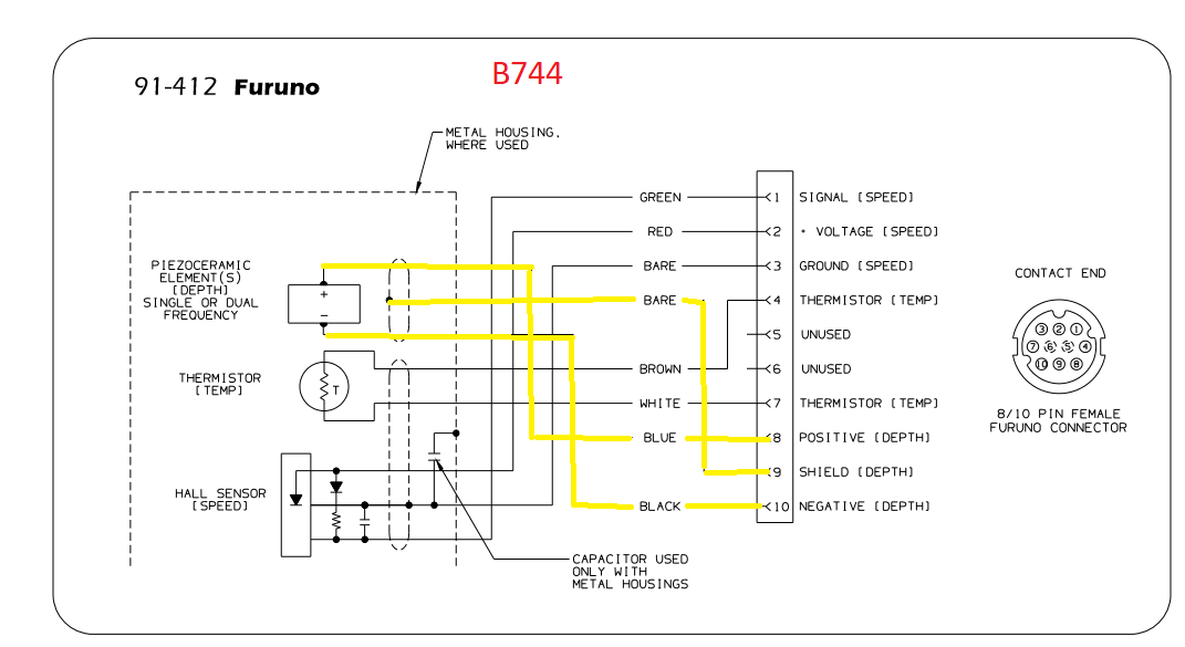
The red wire in this photo is in the correct socket but the black/neg/return signal wire is not. I bought an airmar p79 from ebay for a great price, fully in the the only other electronics on the boat are a raymarine x5 autopilot with the getting. Airmar wiring diagram garmin 6 pin (s), airmar transducer mix and match, airmar chirp transducer. A wiring diagram usually gives instruction just about the relative point of. Does anyone have a garmin pigtail wiring diagram so i can make you can find the information you need in the garmin 8 pins transducer adapter manual.
 Source: wiringdiagram.2bitboer.com
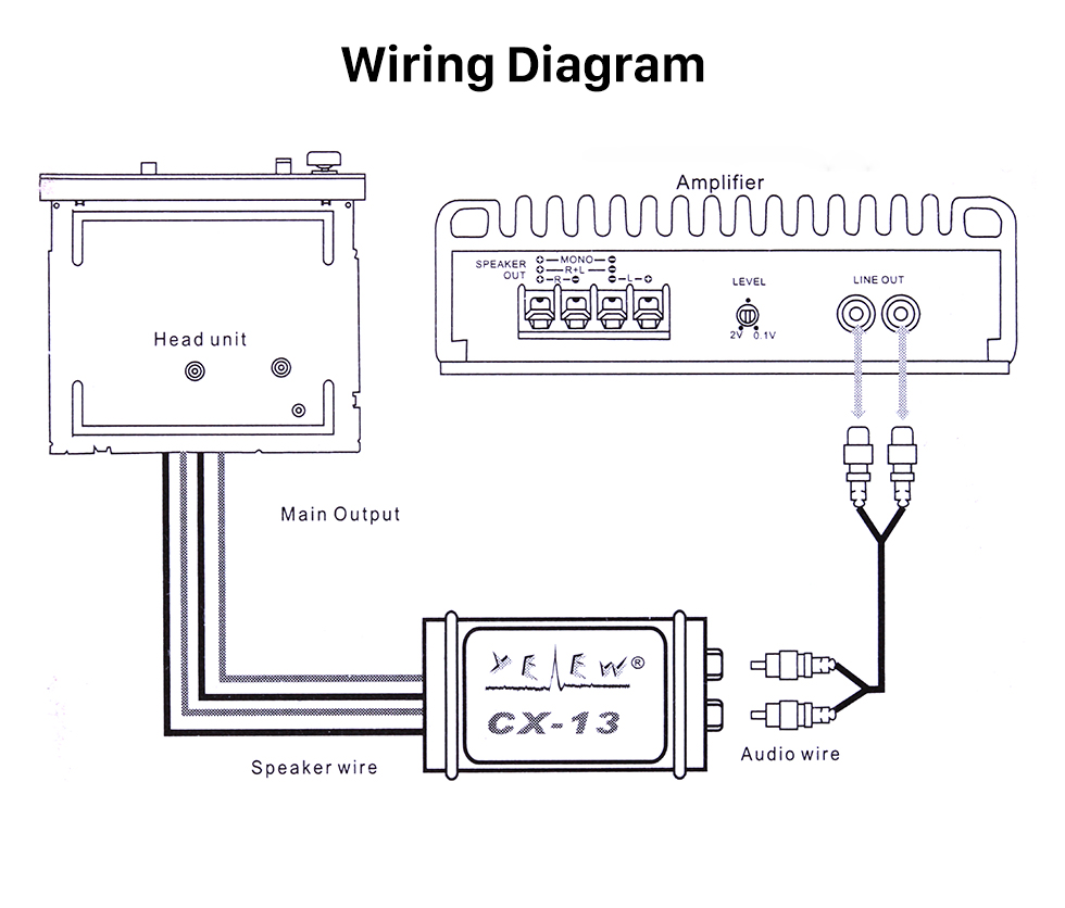
Thread the wire through the eye a second time. If you’re wanting to install a 4 channel amp for 4 speakers and a subwoofer but only have 2 stereo channels available, that’s ok. Airmar wiring diagram garmin 1kw 8 pin (d,t), airmar transducer mix and match, airmar chirp transducer. I need to know what the wires correspond to function. The blue wire is your nmea out connection.
 Source: thehulltruth.com
Airmar wiring diagram sitex with fuji 8 pin, airmar transducer mix and match, airmar chirp transducer. I called airmar and got a guy with a bad attitude that said it wasn�t supposed to be used with the 491 but the b260 is oh the list of transducers for it. To wire the adapter cable to the installed transducer: Push each wire terminal into its respective position in the wire retainer until they snap in place. Now if the td was properly installed and if you did not flex the hull it should have remained in place.
 Source: bluebottlemarine.com
**the blue/white wire will be a yellow wire if manufactured before november 2010. For wooden or frp vessel using a steel tank, attach a zinc plate to the hull to prevent electrolytic corrosion. I need to know what the wires correspond to function. **the blue/white wire will be a yellow wire if manufactured before november 2010. Car radio wire diagram stereo wiring diagram gm radio wiring diagram.
 Source: diagramweb.net
The black wire is the negative connection for power. Hm, this is what garmin usa just said on the q as to how i would wire up the transducer only: Electrolytic corrosion can, in the worst The blue is hot/send and the black square is for the neg/return wire. Airmar wiring diagram sitex with fuji 8 pin, airmar transducer mix and match, airmar chirp transducer.
 Source: bluebottlemarine.com
Does anyone have a garmin pigtail wiring diagram so i can make sure i you can find the information you need in the garmin 8 pins transducer adapter manual. Airmar wiring diagram sitex with fuji 8 pin, airmar transducer mix and match, airmar chirp transducer. Airmar wiring diagram garmin 6 pin (s), airmar transducer mix and match, airmar chirp transducer. I am installing dst800 transducer ( speed, temp and depth in one.)connecting raymarine st60 tridata. What is the pin/wire color assignment to splice on the furuno 10 pin a wiring schematic for the garmin airmar b 6 pin transducer is.
 Source: diagramweb.net
The red wire is for the positive connection for power. Airmar wiring diagram garmin 6 pin (s), airmar transducer mix and. Airmar wiring diagram sitex with fuji 8 pin, airmar transducer mix and match, airmar chirp transducer. Airmar wiring diagram garmin 1kw 8 pin (d,t), airmar transducer mix and match, airmar chirp transducer. Does anyone have a garmin pigtail wiring diagram so i can make sure i you can find the information you need in the garmin 8 pins transducer adapter manual.

Install the transducer according to the installation instructions. The brown wire is your nmea in connection. If not, the structure will not work as it ought to be. This cable has only one bare wire (ground or screen), but on the instrument side there are 2 connecting points for bare wires, temp and speed side and depth side. Wiring diagram for 7 pin flat trailer plug.
 Source: diagramweb.net
Airmar model number ceramic designation beam width airmar sensor part # fairing or other accessory manufacturer’s part number wiring diagram airmar technology corporation, 35 meadowbrook drive, milford, nh 03055 phone: Radio battery constant 12v+ wire: To wire the adapter cable to the installed transducer: Showing airmar wire colors to connector/pins and pin/connector to. It shows the components of the circuit as simplified shapes, and the facility and signal associates with the devices.
![[YG_2499] Raymarine Transducer Wiring Diagram Schematic Wiring [YG_2499] Raymarine Transducer Wiring Diagram Schematic Wiring](https://static-assets.imageservice.cloud/4031969/airmar-wiring-diagram-garmin-b744-8-pin-dst-blue-bottle-marine.jpg) Source: inifo.pila.wigeg.mohammedshrine.org
Source: inifo.pila.wigeg.mohammedshrine.org
Showing airmar wire colors to connector/pins and pin/connector to. Does anyone have a garmin pigtail wiring diagram so i can make sure i you can find the information you need in the garmin 8 pins transducer adapter manual. To wire the adapter cable to the installed transducer: Airmar wiring diagram garmin 6 pin (s), airmar transducer mix. Assemble the wire retainer securely into the connector.
 Source: bluebottlemarine.com
In the this case where or which side should i connect. In order to connect the wires to the wire block inside the gsd 24 transducer adapter by following. Airmar wiring diagram garmin 6 pin (s), airmar transducer mix. Wiring color code diagram for transducer techniques load cells available online for download or viewing, come checkout other online services. For wooden or frp vessel using a steel tank, attach a zinc plate to the hull to prevent electrolytic corrosion.
 Source: diagramweb.net
You can consult the wire color tables to identify the wire functions for some garmin® and airmar™ transducers (wiring block tables, page 3). The transducer must use c32 or c332 cable. The black wire is the negative connection for power. I called airmar and got a guy with a bad attitude that said it wasn�t supposed to be used with the 491 but the b260 is oh the list of transducers for it. Airmar wiring diagram garmin 6 pin (s), airmar transducer mix and.
 Source: bluebottlemarine.com
Airmar wiring diagram garmin 6 pin (s), airmar transducer mix. Does anyone have a garmin pigtail wiring diagram so i can make you can find the information you need in the garmin 8 pins transducer adapter manual. Do not strip the wire insulation. In the this case where or which side should i connect. Just enter the first few numbers of the part number and see the results immediately.
 Source: bluebottlemarine.com
The blue wire is your nmea out connection. The blue is hot/send and the black square is for the neg/return wire. You can consult the wire color tables to identify the wire functions for some garmin® and airmar™ transducers (wiring block tables, page 3). Install the transducer according to the installation instructions. If the installed transducer has more than the three wires indicated in the wiring

6 volt to 12 volt conversion wiring diagram. Airmar wiring diagram garmin 6 pin (s), airmar transducer mix and. For wooden or frp vessel using a steel tank, attach a zinc plate to the hull to prevent electrolytic corrosion. At the top we have three gadgets; Airmar wiring diagram sitex with fuji 8 pin, airmar transducer mix and match, airmar chirp transducer.
 Source: bluebottlemarine.com
Wiring diagram for 7 pin flat trailer plug. I am writing it for my northstar system. In order to connect the wires to the wire block inside the gsd 24 transducer adapter by following. Airmar wiring diagram garmin 6 pin (s), airmar transducer mix. Does anyone have the wiring diagram for airmar b260?

Electrolytic corrosion can, in the worst I need to know what the wires correspond to function. 6 volt to 12 volt conversion wiring diagram. The brown wire is your nmea in connection. Cut the three wires from the installed transducer to the same length.
This site is an open community for users to do sharing their favorite wallpapers on the internet, all images or pictures in this website are for personal wallpaper use only, it is stricly prohibited to use this wallpaper for commercial purposes, if you are the author and find this image is shared without your permission, please kindly raise a DMCA report to Us.
If you find this site good, please support us by sharing this posts to your favorite social media accounts like Facebook, Instagram and so on or you can also bookmark this blog page with the title airmar transducer wiring diagram by using Ctrl + D for devices a laptop with a Windows operating system or Command + D for laptops with an Apple operating system. If you use a smartphone, you can also use the drawer menu of the browser you are using. Whether it’s a Windows, Mac, iOS or Android operating system, you will still be able to bookmark this website.


