
Your Air ride relay wiring diagram images are ready in this website. Air ride relay wiring diagram are a topic that is being searched for and liked by netizens now. You can Find and Download the Air ride relay wiring diagram files here. Download all royalty-free photos and vectors.
If you’re looking for air ride relay wiring diagram images information connected with to the air ride relay wiring diagram keyword, you have visit the ideal blog. Our site always provides you with hints for seeing the highest quality video and image content, please kindly surf and find more informative video articles and images that fit your interests.
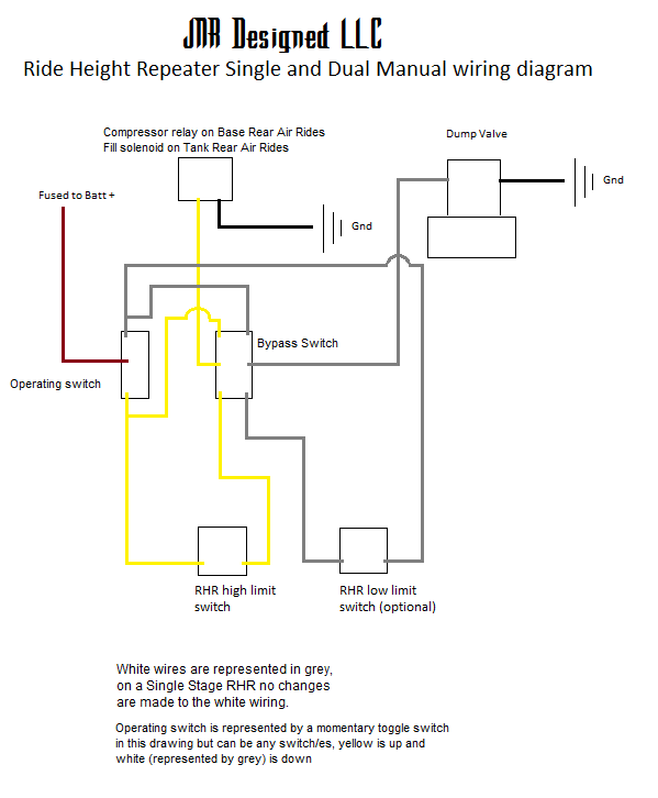
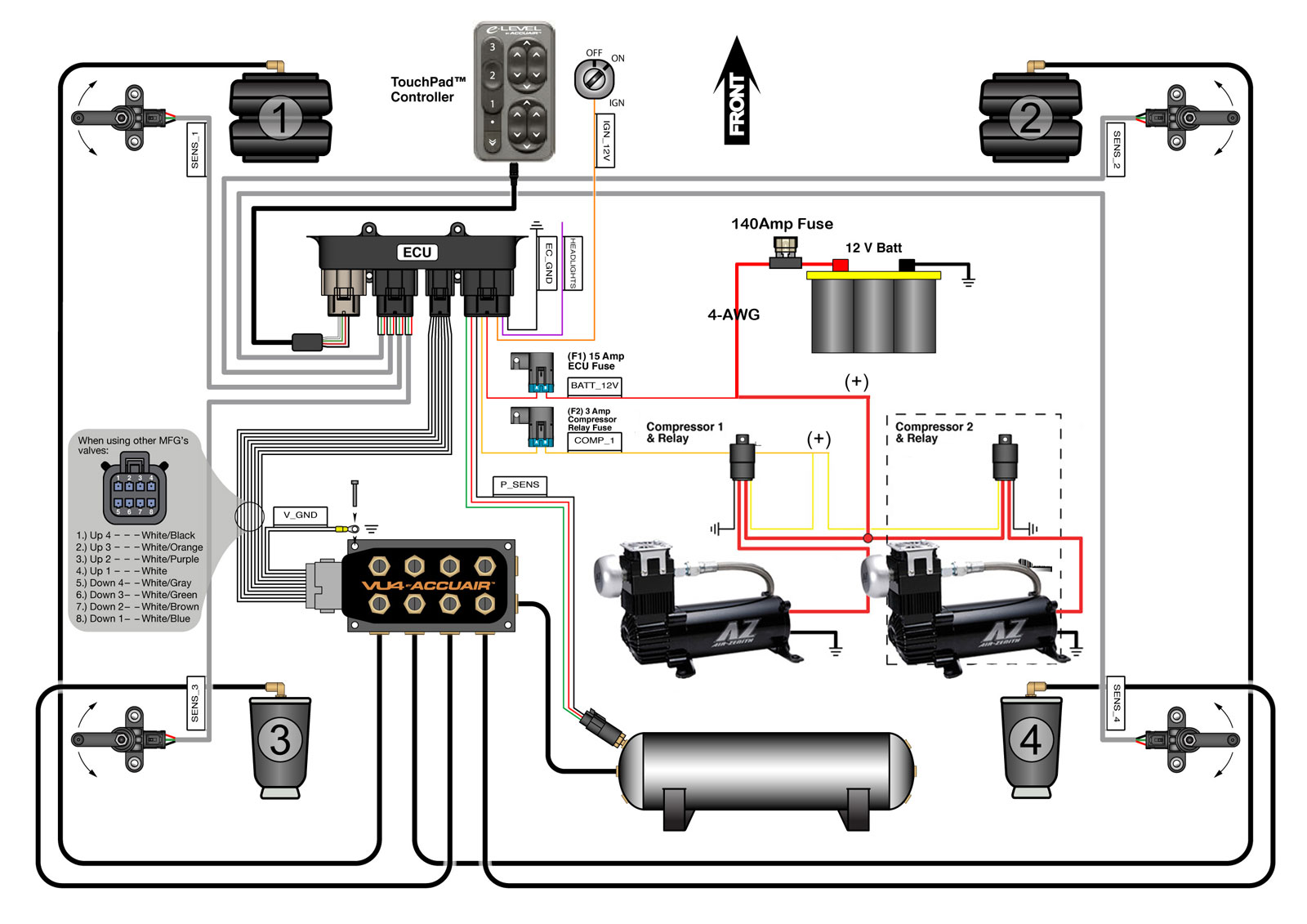
Air Ride Relay Wiring Diagram. • if you are running two compressors you will need an The yellow wire on the relay will go to the red wire on the compressor. Air ride suspension control diagram. Ez air ride dual 444c wiring diagram to tank 12v 40a relay do not use red wire to tank 12v.
 2nd compressor install Air Ride Technologies From ridetech.com
The small gray and orange wires will plug into the rl1 port on the ecu. The system will now have control of the valves but will not display pressures or heights until the sensors are installed. This is what we use on our show quality installations. Use the following diagram for twin compressor setups. Connect pressure switch wire to relay using the supplied connector (blue) to contact # 86 and to contact on the pressure switch 6. Air ride valve wiring diagram wiring diagram is a simplified standard pictorial representation of an electrical circuit.
Connect the lcd controller to the relay control box.
The small gray and orange wires will plug into the rl1 port on the ecu. March 31 2018 by headcontrolsystem. Determine where the lcd controller will be mounted. The small gray and orange wires will plug into the rl1 port on the ecu. Wire according to diagram on page 1. Gm air ride relay wiring diagram desember 26, 2021 posting komentar driving a car with faulty air suspension out of an underground car park and a steep ramp is quite the challenge.
 Source: diagramweb.net
Ez air ride dual 444c wiring diagram to tank 12v 40a relay do not use red wire to tank 12v 40a relay do not use red wire pressure switch to keyed power source either prong fuse battery relays relays help to increase the life expectancy of pressure switches by. Our website frequently gives you suggestions for seeking the maximum quality video and picture content, please kindly search and locate more informative video articles and graphics that. The small gray and orange wires will plug into the rl1 port on the ecu. One of our latest products are the flhfht 4149 55mm 9. Air ride valve wiring diagram wiring diagram is a simplified standard pictorial representation of an electrical circuit.
 Source: easywiring.info
Repairing an electrical problem with your oven is definitely easier when you find the right oven wiring diagram. Fisher an electrical wiring layout is an easy visual representation of the physical links as well as physical design of an electrical system or circuit. With 14 gauge primary wire from second terminal on pressure swirch to small switched terminal on top of the solenoid or terminal 85 on relay. Air ride suspension control diagram. • if you are running two compressors you will need an additional relay that will plug into the rl2 port.
 Source: wiring89.blogspot.com
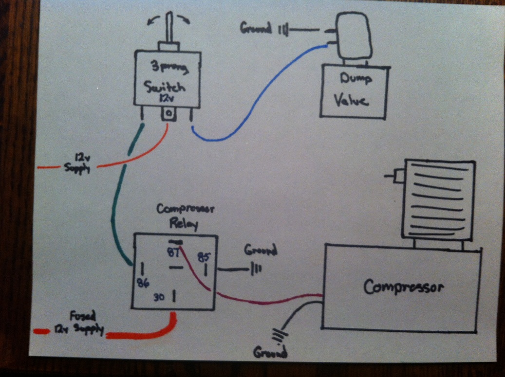
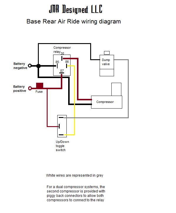
• if you are running two compressors you will need an additional relay that will plug into the rl2 port. Relay wiring diagram manual air ride management kit wiring valve pneumatic diagrams limebug dual c model compressor wiring diagram viair 444c user manual page 7 8 With 14 gauge primary wire from second terminal on pressure swirch to small switched terminal on top of the solenoid or terminal 85 on relay. The black wire on the compressor should be attached to a clean ground, usually the frame. The yellow wire on the relay will go to the red wire on the compressor.
 Source: diagramweb.net
16+ air ride wiring diagram posted on january 21, 2020 august 21, 2020 by joshua j. Air ride valve wiring diagram wiring diagram is a simplified standard pictorial representation of an electrical circuit. They allow a small circuit to govern a future flow circuit using an electromagnet to govern the flow of electricity inside the circuit. My old girl lay down and simply refused to get up. The system will now have control of the valves but will not display pressures or heights until the sensors are installed.
 Source: ridetech.com
My old girl lay down and simply refused to get up. Air shocks, a viair 98 compressor, a dump/solenoid, and relay. This output is only designed to control a compressor with less than a 40 amp load. The system will now have control of the valves but will not display pressures or heights until the sensors are installed. It came with a pressure switch thats going to turn the unit off at psi and turn it on as soon as the pressure in the tank drops under psi.
 Source: jnrdesigned.com
The small gray and orange wires will plug into the rl1 port on the ecu. Air ride suspension control diagram i need to understand how it works and need a wiring diagram. Air ride switch box wiring diagram. Air ride suspension control diagram. The small gray and orange wires will plug into the rl1 port on the ecu.
 Source: pinterest.com
Air ride compressor relay wiring diagram March 31 2018 by headcontrolsystem. My old girl lay down and simply refused to get up. With 14 gauge primary wire from second terminal on pressure swirch to small switched terminal on top of the solenoid or terminal 85 on relay. The yellow wire on the relay will go to the red wire on the compressor.
 Source: hdforums.com
There is a switch attached to the chassis with a rod connecting it to a rear control arm on or near the air pump at the rear of the truckthe switch could be faulty or the rod may. Gm air ride relay wiring diagram desember 26, 2021 posting komentar driving a car with faulty air suspension out of an underground car park and a steep ramp is quite the challenge. This output is only designed to control a compressor with less than a 40 amp load. Ez air ride dual 444c wiring diagram to tank 12v 40a relay do not use red wire to tank 12v 40a relay do not use red wire pressure switch to keyed power source either prong fuse battery relays relays help to increase the life expectancy of pressure switches by protecting them from the high amp draw of the. This wiring kit has everything you need to hook up 2 compressors.
 Source: jnrdesigned.com
Connect the lcd controller to the relay control box. Connect the lcd controller to the relay control box. Air ride suspension control diagram. One of our latest products are the flhfht 4149 55mm 9. Gm air ride relay wiring diagram desember 26, 2021 posting komentar driving a car with faulty air suspension out of an underground car park and a steep ramp is quite the challenge.
 Source: s10forum.com
The small gray and orange wires will plug into the rl1 port on the ecu. 92585e air ride compressor relay wiring diagram wiring. Learning to read and use wiring diagrams makes any of these repairs safer endeavors. 46 out of 5 stars 1889. One of our latest products are the flhfht 4149 55mm 9.
 Source: airride.co.uk
If you’re looking for air ride relay wiring diagram images information related to the air ride relay wiring diagram topic, you have come to the ideal blog. Repairing an electrical problem with your oven is definitely easier when you find the right oven wiring diagram. Fisher an electrical wiring layout is an easy visual representation of the physical links as well as physical design of an electrical system or circuit. This output is only designed to control a compressor with less than a 40 amp load. One of our latest products are the flhfht 4149 55mm 9.
 Source: completeairride.com
Gm air ride relay wiring diagram desember 26, 2021 posting komentar driving a car with faulty air suspension out of an underground car park and a steep ramp is quite the challenge. Air ride suspension control diagram. March 31 2018 by headcontrolsystem. We recommend all items are installed by a qualified individual(s). Fisher an electrical wiring layout is an easy visual representation of the physical links as well as physical design of an electrical system or circuit.
 Source: justanswer.com
The yellow wire on the relay will go to the red wire on the compressor. Air ride relay wiring diagram : Wire according to diagram on page 1. Total amps total length of wire from battery to compressor; Gm air ride relay wiring diagram desember 26, 2021 posting komentar driving a car with faulty air suspension out of an underground car park and a steep ramp is quite the challenge.
 Source: justanswer.com
46 out of 5 stars 1889. The black wire on the compressor should be attached to a clean ground, usually the frame. Connect pressure switch wire to relay using the supplied connector (blue) to contact # 86 and to contact on the pressure switch 6. The system will now have control of the valves but will not display pressures or heights until the sensors are installed. Best bet for a wiring and parts location diagram is alldatadiy.com.
 Source: wiring.hpricorpcom.com
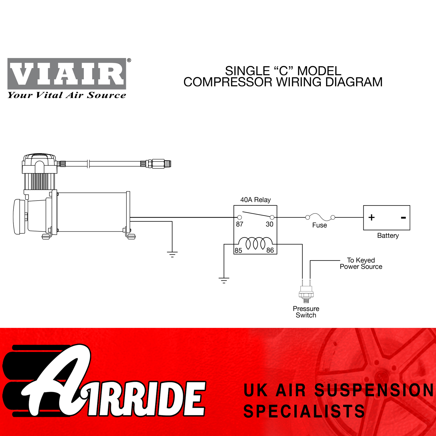
Connect power wire from the compressor (red wire) to the relay on contact #87 5. Air shocks, a viair 98 compressor, a dump/solenoid, and relay. Air ride relay wiring diagram. Determine where the lcd controller will be mounted. Most times these providers have either incomplete or wrong diagrams that can potentially cost the shop wasted time, grant or even possibly a lawsuit.
 Source: s10forum.com
92585e air ride compressor relay wiring diagram wiring. Air ride solenoid wiring diagram wiring diagram is a simplified conventional pictorial representation of an electrical circuit. The black wire on the compressor should be attached to a clean ground, usually the frame. Air ride suspension control diagram. These days, there are several sources that try to allow air ride switch wiring diagram to the mechanic online.
 Source: completeairride.com
These wiring diagrams cover all “c” model viair compressors as included with our manual air ride management kits. Total amps total length of wire from battery to compressor; They allow a small circuit to govern a future flow circuit using an electromagnet to govern the flow of electricity inside the circuit. Air shocks, a viair 98 compressor, a dump/solenoid, and relay. Air ride relay wiring diagram.
 Source: pinterest.com
They allow a small circuit to govern a future flow circuit using an electromagnet to govern the flow of electricity inside the circuit. The black wire on the compressor should be attached to a clean ground, usually the frame. • if you are running two compressors you will need an additional relay that will plug into the rl2 port. Air ride valve wiring diagram wiring diagram is a simplified standard pictorial representation of an electrical circuit. Air ride suspension control diagram.
This site is an open community for users to submit their favorite wallpapers on the internet, all images or pictures in this website are for personal wallpaper use only, it is stricly prohibited to use this wallpaper for commercial purposes, if you are the author and find this image is shared without your permission, please kindly raise a DMCA report to Us.
If you find this site adventageous, please support us by sharing this posts to your own social media accounts like Facebook, Instagram and so on or you can also bookmark this blog page with the title air ride relay wiring diagram by using Ctrl + D for devices a laptop with a Windows operating system or Command + D for laptops with an Apple operating system. If you use a smartphone, you can also use the drawer menu of the browser you are using. Whether it’s a Windows, Mac, iOS or Android operating system, you will still be able to bookmark this website.


