Your Air fuel ratio sensor wiring diagram images are available. Air fuel ratio sensor wiring diagram are a topic that is being searched for and liked by netizens now. You can Download the Air fuel ratio sensor wiring diagram files here. Find and Download all free images.
If you’re searching for air fuel ratio sensor wiring diagram images information related to the air fuel ratio sensor wiring diagram topic, you have pay a visit to the ideal site. Our website frequently gives you hints for viewing the highest quality video and picture content, please kindly hunt and locate more enlightening video content and images that match your interests.
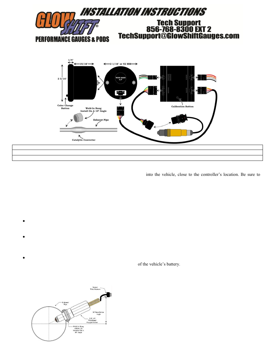
Air Fuel Ratio Sensor Wiring Diagram. It is also known as the broadband lambda sensor or lambda probe. the air fuel ratio sensor is installed in the exhaust manifold or in the front exhaust pipe, before the catalytic converter. How the sensor responds to changes in the air/fuel ratio. All o2 sensors are basically the same, with some being heated or others providing multiple signal lines. Plug a scan tool into the vehicle diagnostic connector, start the engine and create a momentary change in the air/fuel radio by snapping the throttle or feeding propane into the throttle body.
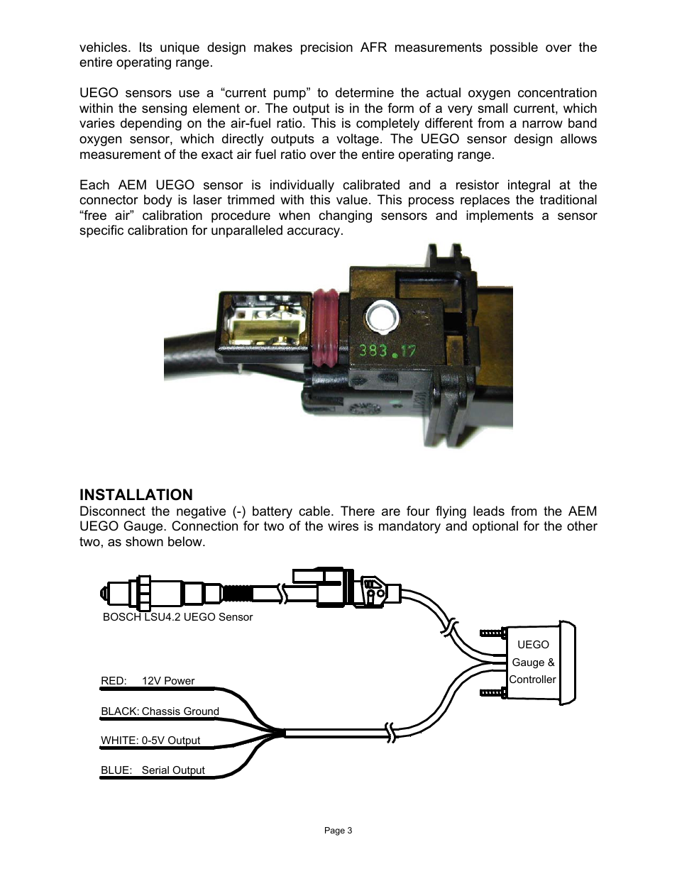
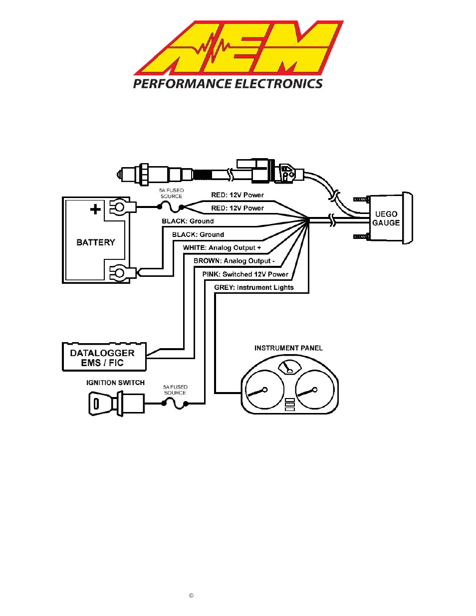
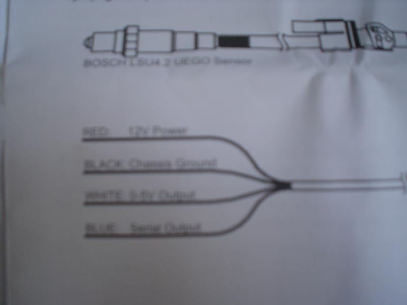 Aem Air Fuel Gauge Wiring Diagram From schematron.org
Secure with supplied bracket and hardware. Air fuel ratio sensor wiring diagram pdf (air_fuel_7634.pdf) download air fuel ratio sensor wiring diagram pdf because nitrous oxide is minimally metabolised in humans with a rate of 0.004% , it retains its potency when exhaled into the room by the patient, and can pose an intoxicating and prolonged exposure hazard to the clinic staff if the. A lambda measurement of “1” equates to the air fuel ratio of 14.7 (for gasoline engines). Mount gauge in 52.4mm diameter hole. Especially today�s more sensitive, turbocharged, and efficient engines. This ratio is called the stoichiometric ratio.
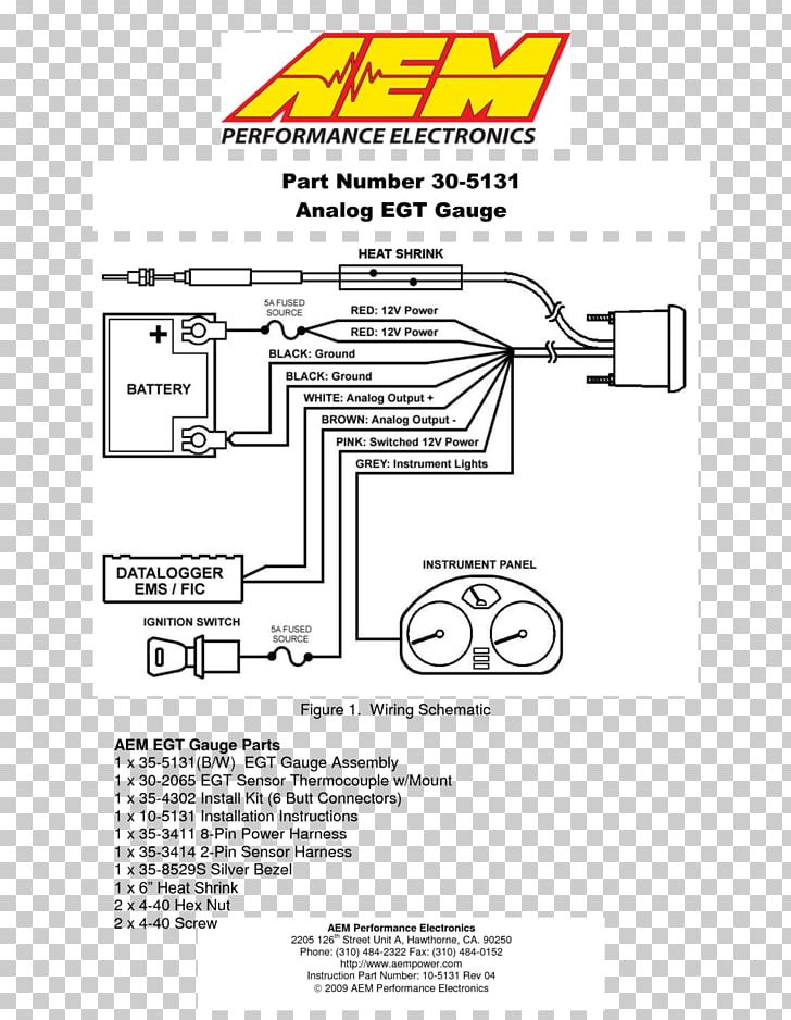
Faze air fuel ratio gauge, led�s, got all the wiring, i even sottered longer wires on to go through the firewall and make it to the o2 sensor and all, lookin to get gauge dashboard bracket nuts (knurled) figure 1 gauge mounting air/fuel ratio gauge installation instructions this gauge was designed for volt, negative ground electrical diagramweb.
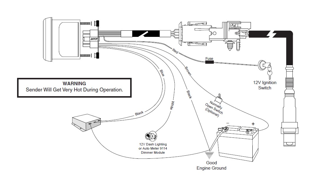
12v ignition switch good engine ground wide open throttle switch (for wot peak function) data logger output red black. The way the sensor was labeled was also confusing, so i made measurements with my dvom and recorded them on my worksheet. Oxygen sensor this sensor produces a voltage signal based on the amount of oxygen it detects in the exhaust stream. Neither will change significantly during mixture variations. Plug a scan tool into the vehicle diagnostic connector, start the engine and create a momentary change in the air/fuel radio by snapping the throttle or feeding propane into the throttle body. Stoichiometric for different fuels are as follows:
 Source: diagramweb.net
The team also supplies the. Bosch 5 wire sensor wiring diagrams around stoich some free oxygen becomes available and the voltage produced by the sensor rapidly drops. Air fuel ratio sensor wiring diagram pdf (air_fuel_7634.pdf) download air fuel ratio sensor wiring diagram pdf because nitrous oxide is minimally metabolised in humans with a rate of 0.004% , it retains its potency when exhaled into the room by the patient, and can pose an intoxicating and prolonged exposure hazard to the clinic staff if the. Gasoline 14.7 lpg (propane) 15.5 methanol 6.4 ethanol 9.0 cng 17.2 diesel 14.6 the measurement lambda is the actual air fuel ratio over the stoichiometric ratio. In nearly all oxygen sensors, a lean mixture (greater than 14.7:1) causes the oxygen sensor output voltage to drop, while a rich mixture (less than 14.7:1) causes the sensor output to go up.

Stoichiometric for different fuels are as follows: The way an engine management system monitors its air / fuel ratio is through the oxygen sensor (o2) stuck in the hot exhaust flow, usually before the catalytic converter. An air/fuel ratio sensor is much like an oxygen sensor, or o2 sensor, and is slowly replacing them on many vehicles. Faze air fuel ratio gauge, led�s, got all the wiring, i even sottered longer wires on to go through the firewall and make it to the o2 sensor and all, lookin to get gauge dashboard bracket nuts (knurled) figure 1 gauge mounting air/fuel ratio gauge installation instructions this gauge was designed for volt, negative ground electrical diagramweb. Lot of 3 aem air fuel gauge, greddy turbo boost and greddy exhaust temperature gauge (gauge only).
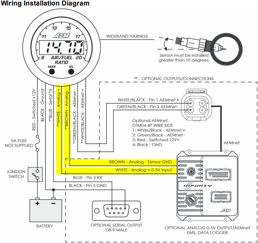 Source: wiringdiagram.2bitboer.com
If either one or both of these wires are not being used, isolate and tape the wire(s) in an out of the way location. All o2 sensors are basically the same, with some being heated or others providing multiple signal lines. Secure with supplied bracket and hardware. Engine, splice the other signal wire to the oxygen sensor signal circuit on bank 2 of the engine.this allows the leds on the right side of the gauge to display the air/fuel ratio for bank 1 oxygen sensor and the leds on the left side of the gauge to display the air/fuel ratio for bank 2 oxygen sensor (see figure 3). It might also be called �front o2 sensor�.
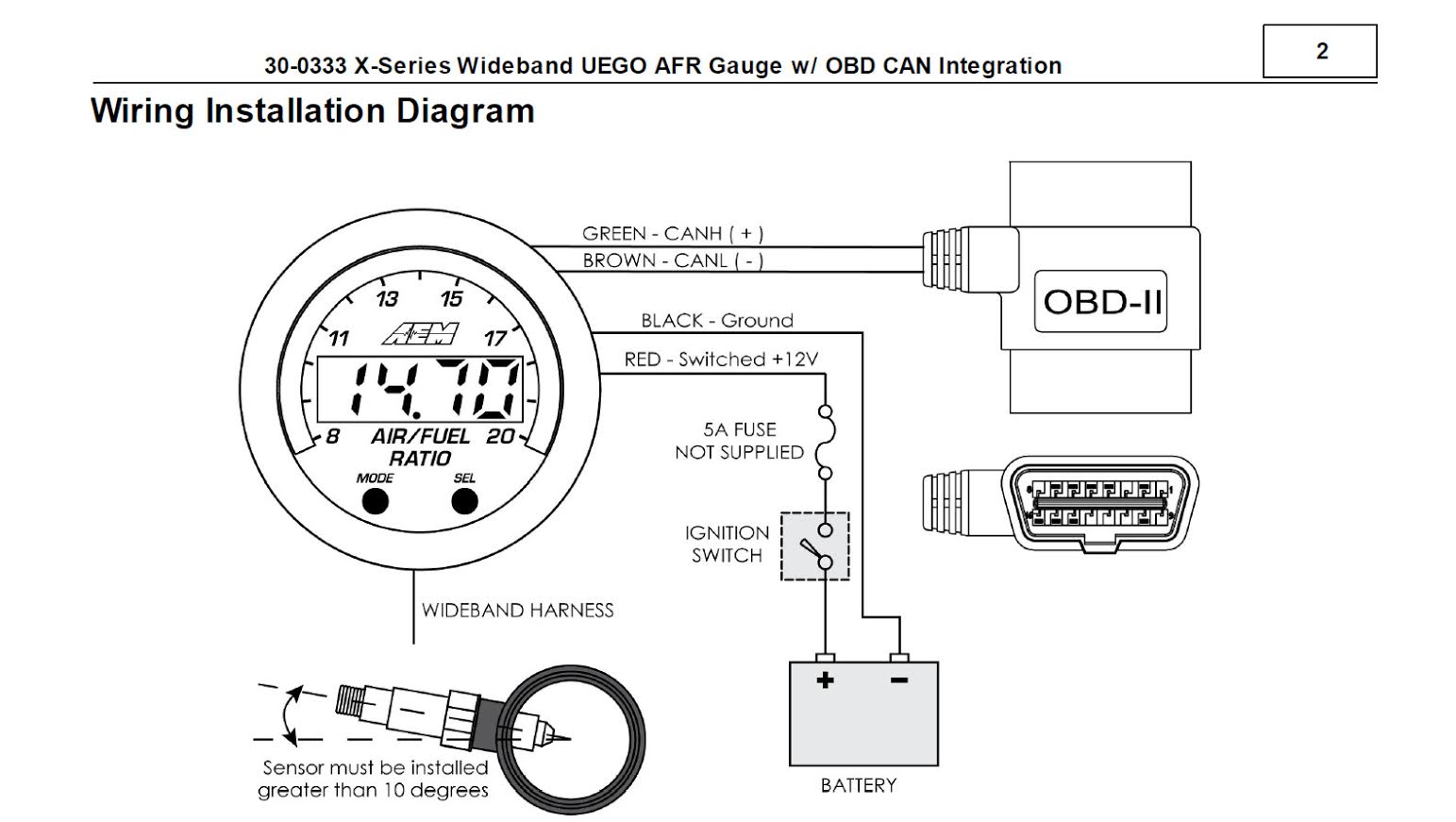 Source: corvetteonline.com
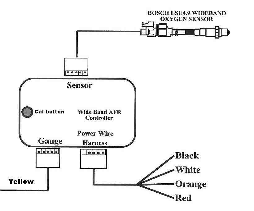
Analog output one (yellow) is 0v = 7.35 afr and 5v = 22.39 afr. The auto meter air/fuel gauge has a signal output for supplying information to a data logger or engine management system. This ratio is called the stoichiometric ratio. Especially today�s more sensitive, turbocharged, and efficient engines. Plug a scan tool into the vehicle diagnostic connector, start the engine and create a momentary change in the air/fuel radio by snapping the throttle or feeding propane into the throttle body.
 Source: ryanandkatiedoughan.blogspot.com
The default analog outputs are as follows: Hopefully you are all enjoy and finally will get the best picture from our collection that submitted here and also use for suited needs for personal use. It is also known as the broadband lambda sensor or lambda probe. the air fuel ratio sensor is installed in the exhaust manifold or in the front exhaust pipe, before the catalytic converter. Especially today�s more sensitive, turbocharged, and efficient engines. Wire gauge as shown in diagram.
 Source: smarts4k.com
An air/fuel ratio sensor is much like an oxygen sensor, or o2 sensor, and is slowly replacing them on many vehicles. 01.05.2012 · brand new bosch 4 wire 02 sensors no faults for 02 sensors at all i have an email into techrods but have not heard back yet just looking for some help reply like. The way the sensor was labeled was also confusing, so i made measurements with my dvom and recorded them on my worksheet. Air fuel ratio (a/f) sensor: Dtc p2a00 may be set when the air fuel ratio is stuck rich or lean.
 Source: wiringdiagram.2bitboer.com
The way an engine management system monitors its air / fuel ratio is through the oxygen sensor (o2) stuck in the hot exhaust flow, usually before the catalytic converter. Plug a scan tool into the vehicle diagnostic connector, start the engine and create a momentary change in the air/fuel radio by snapping the throttle or feeding propane into the throttle body. An air/fuel ratio sensor is much like an oxygen sensor, or o2 sensor, and is slowly replacing them on many vehicles. 2 k 2 knock sensor no. Press the gauge into the mounting kit.
 Source: manualsdir.com
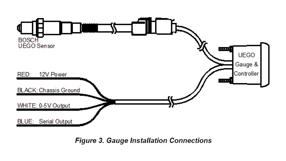
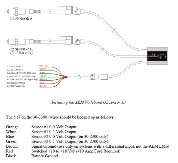
01.05.2012 · brand new bosch 4 wire 02 sensors no faults for 02 sensors at all i have an email into techrods but have not heard back yet just looking for some help reply like. Disconnect vehicle battery before installation. The uego sensor harness simply needs to be routed to the uego sensor whereas the power/io harness will require further integration into the vehicle. The digital imagery with the title aem analog wideband uego gauge fuel afr user guide within aem air gas wiring diagram above, is tagged with: All o2 sensors are basically the same, with some being heated or others providing multiple signal lines.
 Source: americanmuscle.com
What i foun out there is only 4 wire regular narrow band o2. Oxygen sensor this sensor produces a voltage signal based on the amount of oxygen it detects in the exhaust stream. All o2 sensors are basically the same, with some being heated or others providing multiple signal lines. Bosch oxygen sensor wiring diagram 3 wires. Check for conditions that would cause the engine to run rich.
 Source: diagramweb.net
Dtc p2a00 may be set when the air fuel ratio is stuck rich or lean. If the oxygen sensor has 2, 3, or 4 wires, consult wiring diagram for your vehicle or contact vehicle manufacturer to identify the signal wire. The digital imagery with the title aem analog wideband uego gauge fuel afr user guide within aem air gas wiring diagram above, is tagged with: An air/fuel ratio sensor is much like an oxygen sensor, or o2 sensor, and is slowly replacing them on many vehicles. Air fuel ratio (a/f) sensor:

Volvo d13 nox sensor bank 1 sensor 2 am 2416072784. The auto meter air/fuel gauge has a signal output for supplying information to a data logger or engine management system. Disconnect vehicle battery before installation. I have sx4 2010 with 5 wire air fuel ratio oxygen sensor (wideband o2). Check for conditions that would cause the engine to run rich.
 Source: wiringdiagram.2bitboer.com
The uego sensor harness simply needs to be routed to the uego sensor whereas the power/io harness will require further integration into the vehicle. Press the gauge into the mounting kit. The auto meter air/fuel gauge has a signal output for supplying information to a data logger or engine management system. Bosch oxygen sensor wiring diagram 3 wires. The team also supplies the.
 Source: americantrucks.com
Aem, air, diagram, gas, gauge, wiring, aem air gasoline gauge wiring diagram. Especially today�s more sensitive, turbocharged, and efficient engines. Neither will change significantly during mixture variations. Due to the limitations of the sensor, the indicated air/fuel ratio Oxygen sensor this sensor produces a voltage signal based on the amount of oxygen it detects in the exhaust stream.
 Source: wiringdiagramsx.blogspot.com
01.05.2012 · brand new bosch 4 wire 02 sensors no faults for 02 sensors at all i have an email into techrods but have not heard back yet just looking for some help reply like. The air fuel ratio (a/f) sensor measures oxygen content of the exhaust in a wider range. Press the gauge into the mounting kit. An air/fuel ratio sensor is much like an oxygen sensor, or o2 sensor, and is slowly replacing them on many vehicles. Lot of 3 aem air fuel gauge, greddy turbo boost and greddy exhaust temperature gauge (gauge only).
 Source: americanmuscle.com
All o2 sensors are basically the same, with some being heated or others providing multiple signal lines. 0 volts out equals 10.0 air/fuel ratio, 4 volts out equals 18.0 air/fuel ratio. Unlike the vulnerable o2 sensor, an air/fuel ratio sensor is a wide range sensor rather than narrow range, and it operates by conduction rather than. If the oxygen sensor has 2, 3, or 4 wires, consult wiring diagram for your vehicle or contact vehicle manufacturer to identify the signal wire. They are so many great picture list that could become your motivation and informational purpose of air fuel ratio gauge wiring diagram design ideas for your own collections.
 Source: chanish.org
What i foun out there is only 4 wire regular narrow band o2. Gasoline 14.7 lpg (propane) 15.5 methanol 6.4 ethanol 9.0 cng 17.2 diesel 14.6 the measurement lambda is the actual air fuel ratio over the stoichiometric ratio. They are so many great picture list that could become your motivation and informational purpose of air fuel ratio gauge wiring diagram design ideas for your own collections. This ratio is called the stoichiometric ratio. Press the gauge into the mounting kit.
 Source: diagramweb.net
Oxygen sensor this sensor produces a voltage signal based on the amount of oxygen it detects in the exhaust stream. Plug a scan tool into the vehicle diagnostic connector, start the engine and create a momentary change in the air/fuel radio by snapping the throttle or feeding propane into the throttle body. I have sx4 2010 with 5 wire air fuel ratio oxygen sensor (wideband o2). Press the gauge into the mounting kit. Lot of 3 aem air fuel gauge, greddy turbo boost and greddy exhaust temperature gauge (gauge only).
 Source: wiringdiagramsx.blogspot.com
Powersafe relay.an air fuel gauge can be connected much easier than you might. 2 k 2 knock sensor no. 2x o2 02 oxygen sensor upstream 12499877 for 2004 2005 2006. A lambda measurement of “1” equates to the air fuel ratio of 14.7 (for gasoline engines). What i foun out there is only 4 wire regular narrow band o2.
This site is an open community for users to submit their favorite wallpapers on the internet, all images or pictures in this website are for personal wallpaper use only, it is stricly prohibited to use this wallpaper for commercial purposes, if you are the author and find this image is shared without your permission, please kindly raise a DMCA report to Us.
If you find this site beneficial, please support us by sharing this posts to your preference social media accounts like Facebook, Instagram and so on or you can also save this blog page with the title air fuel ratio sensor wiring diagram by using Ctrl + D for devices a laptop with a Windows operating system or Command + D for laptops with an Apple operating system. If you use a smartphone, you can also use the drawer menu of the browser you are using. Whether it’s a Windows, Mac, iOS or Android operating system, you will still be able to bookmark this website.

