Your Agility trailer brake controller wiring diagram images are ready in this website. Agility trailer brake controller wiring diagram are a topic that is being searched for and liked by netizens today. You can Get the Agility trailer brake controller wiring diagram files here. Find and Download all free photos.
If you’re searching for agility trailer brake controller wiring diagram images information related to the agility trailer brake controller wiring diagram keyword, you have pay a visit to the right site. Our site always provides you with hints for viewing the highest quality video and picture content, please kindly hunt and locate more informative video content and images that match your interests.
Agility Trailer Brake Controller Wiring Diagram. The following diagram is a general guide for wiring common brake controllers into cars. This black wire will also maintain the charge on your trailer battery while the vehicle is running. Agility trailer brake controller wiring diagram trailer brake controller wiring diagram. When you make use of your finger or perhaps the actual circuit with your eyes, it is easy to mistrace the circuit.
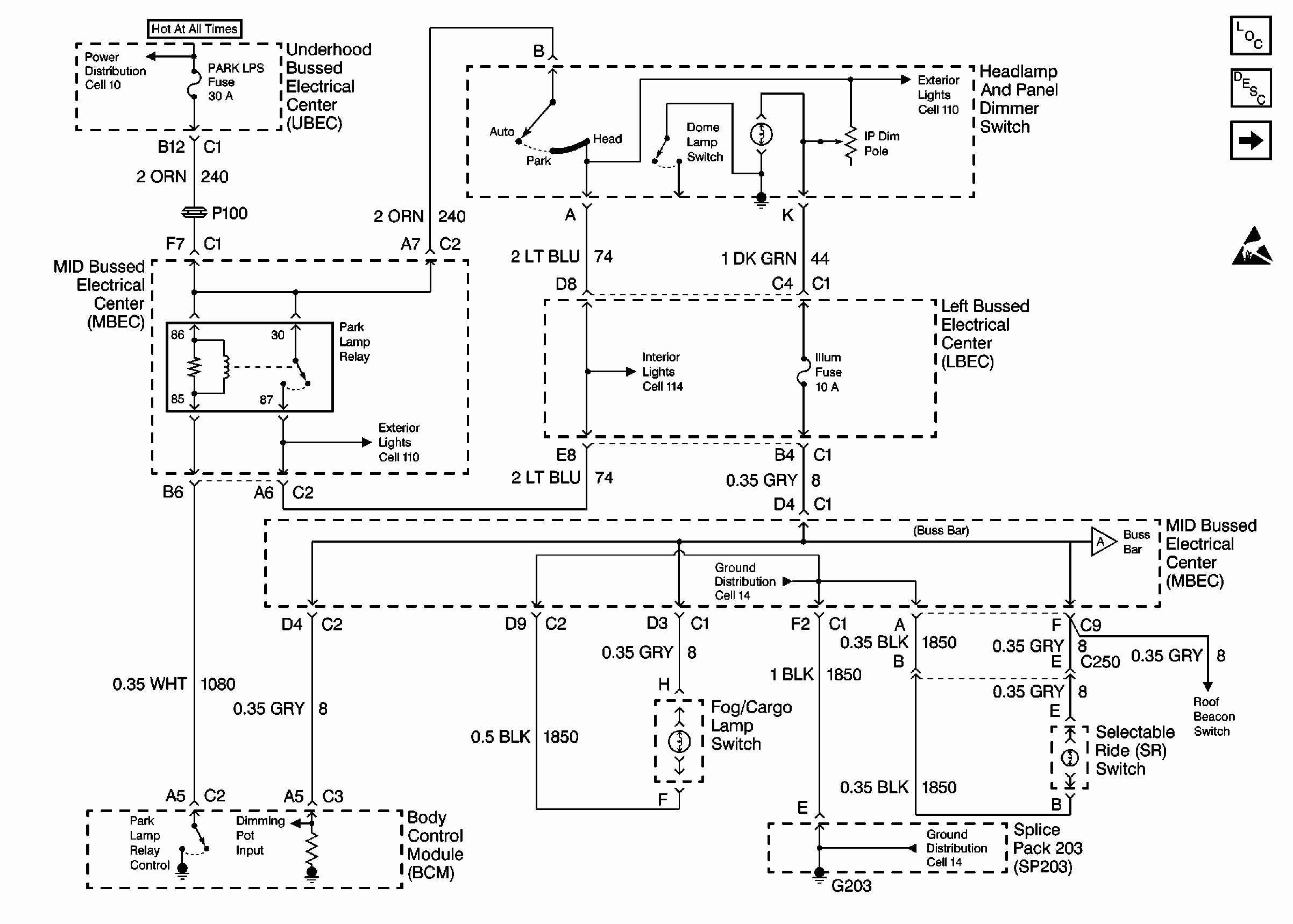
 Agility Trailer Brake Controller Wiring Diagram Top Dodge From tonetastic.info
A brake controller is frequently set up after a trailer purchase to assist in, you guessed it, braking a towing vehicle with a trailer attached. The white wire on the brake controller will be connected to the negative battery terminal. The following diagram is a general guide for wiring common brake controllers into cars. This black wire will also maintain the charge on your trailer battery while the vehicle is running. Brake controller wire functions by color etrailer com owners manual for the hopkins agility trailer hm47295 control wiring diagram to stop light switch on 2011 jeep liberty troubleshooting installations installing a 2010 ford f 150. Splice down line from the switch;
It includes guidelines and diagrams for various types of wiring strategies along with other items like lights, home windows, and so on.
Hopkins brake controller wiring diagram. Agility trailer brake controller wiring diagram. The red (stoplight) wire must be connected to the cold side of the brake pedal stoplight switch. Agility trailer brake controller wiring diagram trailer brake controller wiring diagram. As stated previous, the traces at a trailer brake controller wiring diagram signifies wires. Attach the brake control to the bracket using the slotted hex screws provided (g).
![[DIAGRAM] 7 Way Wiring Diagram Brake Controller FULL](http://trailer-wiring-diagram.com/wp-content/uploads/2019/02/curt-brake-controller-wiring-diagram-hastalavista-wiring-diagram-for-trailer-brake-controller.png "[DIAGRAM] 7 Way Wiring Diagram Brake Controller FULL") Source: diagramssedui.ilpeocio.it
Source: diagramssedui.ilpeocio.it
Hopkins agility brake controller fit owners manual for the trailer control wiring diagram to stop on a 2010 ford f 150 troubleshooting how wire reliance impulse 47235 plug in simple part 54 83504 brakeman iv digital proportional u haul electric 17 dream tools ideas metal 31691 husky towing system kymco 125 city connector. Injunction of 2 wires is generally indicated by black dot to the junction of two lines. It includes guidelines and diagrams for various types of wiring strategies along with other items like lights, home windows, and so on. A brake controller wiring installation kit makes light work! A brake controller is frequently set up after a trailer purchase to assist in, you guessed it, braking a towing vehicle with a trailer attached.
 Source: trailer-wiring-diagram.com
Hopkins agility proportional brake control 8 brake. If playback doesn�t begin shortly, try restarting. The blue wire will connect to the white wire in the duplex cable that you ran up earlier. The blue is electric brake wire, it will connect to the white wire of the duplex wire in the # etbc7 kit which will then connect to the blue electric brake wire. Electric brake controller wiring diagram.
 Source: diagramweb.net
The blue (brake output) wire must be connected to the trailer connector’s brake wire. To hunt for wiring diagrams or making numerous unnecessary connections. Injunction of 2 wires is generally indicated by black dot to the junction of two lines. Brake controller installation starting from scratch etrailer com owners manual for the hopkins agility trailer hm47295 wiring to stop light switch on 2011 jeep. The blue is electric brake wire, it will connect to the white wire of the duplex wire in the # etbc7 kit which will then connect to the blue electric brake wire.
 Source: 356journals.blogspot.com
Agility trailer brake controller wiring diagram jumat, 07 januari 2022 edit. This sort of connector is ideal for consumer trailers. Agility trailer brake controller wiring diagram. Hopkins agility brake controller fit owners manual for the trailer control wiring diagram to stop on a 2010 ford f 150 troubleshooting how wire reliance impulse 47235 plug in simple part 54 83504 brakeman iv digital proportional u haul electric 17 dream tools ideas metal 31691 husky towing system kymco 125 city connector. Beranda › diagram › images › trailer › wiring.
 Source: tonetastic.info
Hopkins 7 pin trailer wiring diagram with brakes.august 18 2021 7 pin trailer wiring diagram by trafalgar d. Attach the brake control to the bracket using the slotted hex screws provided (g). 1 trick that we 2 to printing a similar wiring plan off twice. Refer to product instructions and locate wires on vehicle by function only. Brake controller wire functions by color etrailer com owners manual for the hopkins agility trailer hm47295 control wiring diagram to stop light switch on 2011 jeep liberty troubleshooting installations installing a 2010 ford f 150.
 Source: tonetastic.info
Electric brake controller wiring diagram. Easy gain adjustments and a digital display will make setting this brake control a snap. Agility trailer brake controller wiring diagram trailer brake controller wiring diagram. Wire by using a circuit tester and probing for the wire adjust the brake control to the desired angle and tighten screws until snug. Hopkins impulse electric brake controller 47235.
 Source: wiringdiagram.2bitboer.com
Wiring diagram for agility brake controller. Agility trailer brake controller wiring diagram. It represents the power circuits components as simple shapes, with all the real power and terrain relationships between them as shaded sectors. Hopkins agility trailer brake controller hardwire 1 to 4 axles proportional hopkins trailer br gadget gifts rv stuff best trailers. A wiring diagram is a simplified classic pictorial depiction of an power.
 Source: tonetastic.info
Do not disturb the position of the switch. Hopkins impulse electric brake controller 47235. Agility trailer brake controller wiring diagram cleaver is a free worksheet for you. Electric brake controller wiring diagram. Agility™ electronic brake control important:
 Source: wiringdiagram.2bitboer.com
1 trick that we 2 to printing a similar wiring plan off twice. Agility trailer brake controller wiring diagram. Agility trailer brake controller wiring diagram trailer brake controller wiring diagram. As stated previous, the traces at a trailer brake controller wiring diagram signifies wires. Each component ought to be placed and linked to other parts…
 Source: tonetastic.info
January 29, 2019 april 12, 2020 · wiring diagram by anna r. Beranda › diagram › images › trailer › wiring. This wallpaper was uploaded at march 23, 2021 by tamble in trailer. Wiring diagram for agility brake controller. If not is there a wiring diagram?
 Source: tonetastic.info
To hunt for wiring diagrams or making numerous unnecessary connections. Hopkins agility trailer brake controller hardwire 1 to 4 axles proportional hopkins trailer br gadget gifts rv stuff best trailers. Hopkins 7 pin trailer wiring diagram with brakes.august 18 2021 7 pin trailer wiring diagram by trafalgar d. Agility trailer brake controller wiring diagram trailer brake controller wiring diagram. Injunction of 2 wires is generally indicated by black dot to the junction of two lines.
 Source: tonetastic.info
Brake controller wire functions by color etrailer com owners manual for the hopkins agility trailer hm47295 control wiring diagram to stop light switch on 2011 jeep liberty troubleshooting installations installing a 2010 ford f 150. It includes guidelines and diagrams for various types of wiring strategies along with other items like lights, home windows, and so on. With brake pedal · no trailer brake lights when towed by chevy silverado with hopkins brake controller.ebay determines this price through a machine learned model of the product�s sale prices within the last 90 days. The black wire is the power supply line to the brake control. Trailer brake controller wiring diagram agility trailer brake controller wiring diagram curt trailer brake controller wiring diagram dodge trailer brake controller wiring diagram people today comprehend that trailer is a vehicle comprised of quite complicated mechanisms.
 Source: trailer-wiring-diagram.com
Agility™ electronic brake control important: Agility trailer brake controller wiring diagram trailer brake controller wiring diagram. Wire by using a circuit tester and probing for the wire adjust the brake control to the desired angle and tighten screws until snug. At times, the wires will cross. Wiring diagram for agility brake controller.
Source: tonetastic.info
But, it doesn’t mean connection between the wires. This black wire will also maintain the charge on your trailer battery while the vehicle is running. Using larger/longer screws may damage the unit. It includes guidelines and diagrams for various types of wiring strategies along with other items like lights, home windows, and so on. The red (stoplight) wire must be connected to the cold side of the brake pedal stoplight switch.
 Source: tonetastic.info
The 47294 brake control utilizes proportional braking technology for safe and smooth stops, making you feel like you aren�t even towing a trailer! Hopkins 7 pin trailer wiring diagram with brakes.august 18 2021 7 pin trailer wiring diagram by trafalgar d. To hunt for wiring diagrams or making numerous unnecessary connections. Hopkins agility trailer brake controller hardwire 1 to 4 axles proportional. To make wiring a brake controller easy and cost efficient.
 Source: wiringdiagramharnessideas.blogspot.com
Wiring diagram for agility brake controller. 1 trick that we 2 to printing a similar wiring plan off twice. Wiring diagram includes many in depth illustrations that present the link of assorted products. Splice down line from the switch; The following diagram is a general guide for wiring common brake controllers into cars.
 Source: hanenhuusholli.blogspot.com
Trailer brake controller wiring diagram agility trailer brake controller wiring diagram curt trailer brake controller wiring diagram dodge trailer brake controller wiring diagram people today comprehend that trailer is a vehicle comprised of quite complicated mechanisms. Agility trailer brake controller wiring diagram. This black wire will also maintain the charge on your trailer battery while the vehicle is running. The black wire will be connected to the positive battery terminal via 20 or 30 amp circuit breaker, as specified in the brake controller instructions. The black wire is the power supply line to the brake control.
 Source: tonetastic.info
Wiring diagram for agility brake controller. Brake controller installation starting from scratch etrailer com owners manual for the hopkins agility trailer hm47295 wiring to stop light switch on 2011 jeep. The black wire is the power supply line to the brake control. Injunction of 2 wires is generally indicated by black dot to the junction of two lines. Agility trailer brake controller wiring diagram trailer brake controller wiring diagram.
This site is an open community for users to do sharing their favorite wallpapers on the internet, all images or pictures in this website are for personal wallpaper use only, it is stricly prohibited to use this wallpaper for commercial purposes, if you are the author and find this image is shared without your permission, please kindly raise a DMCA report to Us.
If you find this site serviceableness, please support us by sharing this posts to your favorite social media accounts like Facebook, Instagram and so on or you can also bookmark this blog page with the title agility trailer brake controller wiring diagram by using Ctrl + D for devices a laptop with a Windows operating system or Command + D for laptops with an Apple operating system. If you use a smartphone, you can also use the drawer menu of the browser you are using. Whether it’s a Windows, Mac, iOS or Android operating system, you will still be able to bookmark this website.