Your Aftermarket steering column wiring diagram images are ready. Aftermarket steering column wiring diagram are a topic that is being searched for and liked by netizens today. You can Get the Aftermarket steering column wiring diagram files here. Download all royalty-free images.
If you’re searching for aftermarket steering column wiring diagram pictures information linked to the aftermarket steering column wiring diagram topic, you have visit the right site. Our site always provides you with suggestions for seeking the maximum quality video and picture content, please kindly surf and find more informative video articles and images that match your interests.
Aftermarket Steering Column Wiring Diagram. Wiring up your new steering column can seem like a terrifying task. Found this link here, not a wiring diagram but i did find the correct wire to turn the starter. The first element is emblem that indicate electrical component from the circuit. You may be concerned that you could wire up something wrong, and that’s why our friends at ididit, inc.
 1965 Chevrolet Steering Column Sbc Wiring Diagram From diagramweb.net
- horn power, 2) brake switch, 3) turn flasher. If no hole is in the tube, drill a hold so the tab will align. The standard gm wiring diagram for this plug is: Next install the canceling cam spring over the column shaft and down to the 5/8” alumi num spacer.(figure b) 3. But, it doesn’t imply connection between the wires. Also the wiring diagram is in perspective as if you are looking at the plug from sitting in the seat, the left is pin 1 the right is pin 6.
Many aftermarket steering columns also use these same connectors (i.e.
Sometimes, the cables will cross. As stated earlier, the lines at a ididit steering column wiring diagram signifies wires. The turn signal kit allows the electrical connection of vehicle harness wires to aftermarket, or factory gm steering column with either the 3 7/8 and 4 1/4 11 way turn signal and horn master connector. The manual was pretty good at telling you what to wire to but still need to check. A mate to the 3 7/8 inch plug is available through ididit. So i was investigating some wiring stuff to do with my rear defroster on my 1998 sahara and came across the aftermarket wiring underneath the steering column, when i was checking the cluster.
 Source: 2020cadillac.com
I metered it out once i found the location of the ignition plug on the column, and it follows through the bulkhead connector to what i. You may be concerned that you could wire up something wrong, and that’s why our friends at ididit, inc. Install the lower bearing assembly and dust shield into the tail of the column jacket using a 1/4 socket. The manual was pretty good at telling you what to wire to but still need to check. S4 is the horn button and k2 is the horn relay.
 Source: wiringforums.com
Sometimes, the cables will cross. You may be concerned that you could wire up something wrong, and that’s why our friends at ididit, inc. The standard gm wiring diagram for this plug is: So i was investigating some wiring stuff to do with my rear defroster on my 1998 sahara and came across the aftermarket wiring underneath the steering column, when i was checking the cluster. I agree with retroron, they should have a diagram but will require you to figure out which wire is which in your column.
 Source: 2020cadillac.com
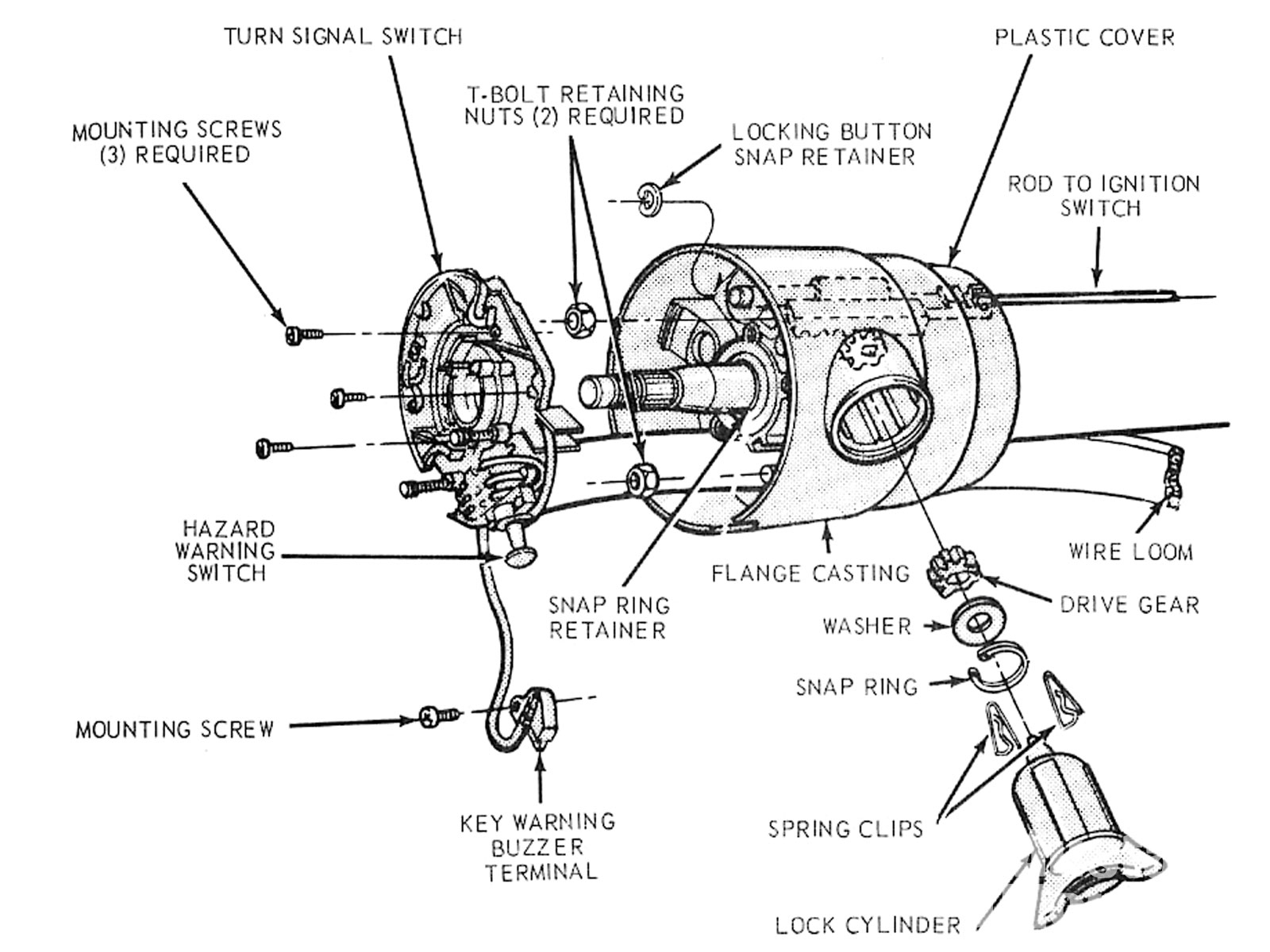
Many aftermarket steering columns also use these same connectors (i.e. Install the large 5/8”aluminum spacer over the column shaft. But, it doesn’t imply connection between the wires. There are just two things which are going to be found in any chevy steering column wiring diagram. Inside the gm tilt steering column page 5.
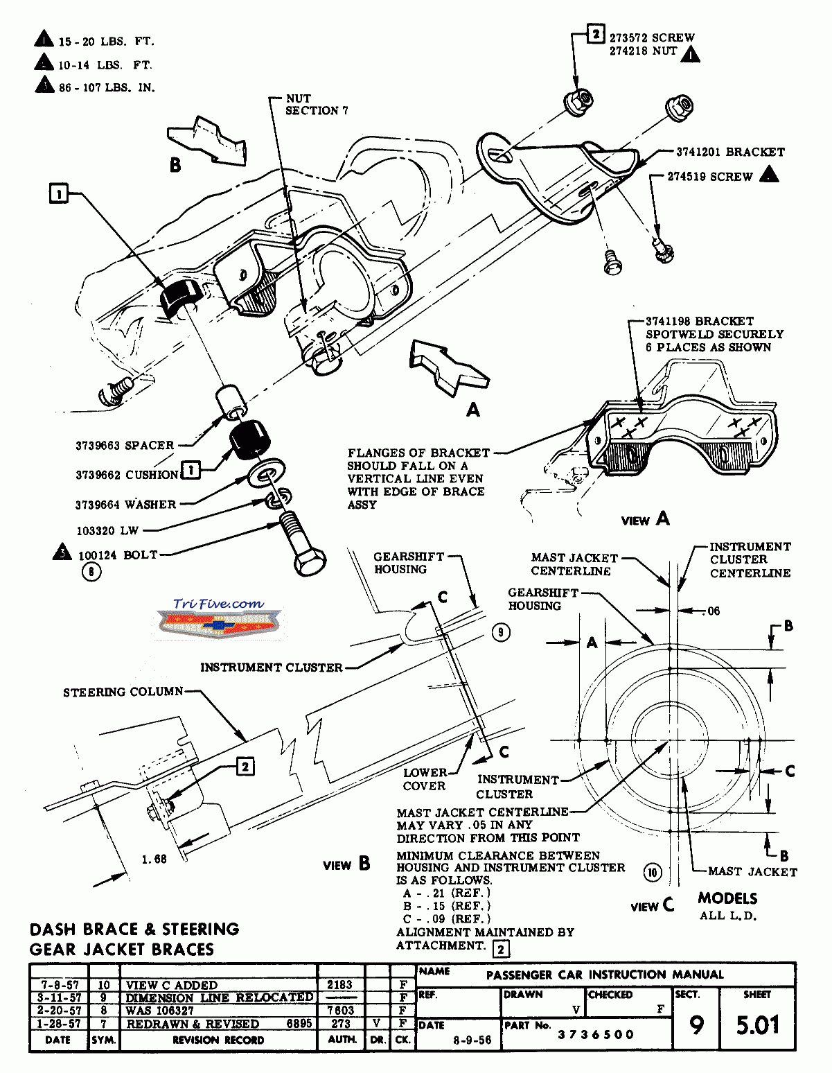 Source: 2020cadillac.com
Wiring diagram includes numerous in depth illustrations that display the connection of varied items. We start assembly with the core part, the column jacket assembly: I metered it out once i found the location of the ignition plug on the column, and it follows through the bulkhead connector to what i. Injunction of 2 wires is usually indicated by black dot to the junction of two lines. Also the wiring diagram is in perspective as if you are looking at the plug from sitting in the seat, the left is pin 1 the right is pin 6.
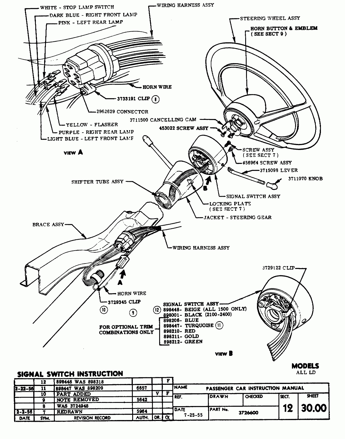 Source: 2020cadillac.com
It includes guidelines and diagrams for various kinds of wiring strategies and other items like lights, home windows, and so on. There are just two things which are going to be found in any chevy steering column wiring diagram. I bought an aftermarket steering wheel and need to connect the horn. Put together a short video outlining what you’ll find when it comes time to make the “connection. This is exactly how they were in the stock ford harness, i.
 Source: wiringforums.com
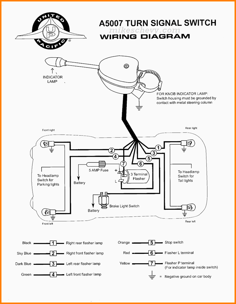
Left turn signal wiring diagram light blue (left front ts) yellow (left rear ts) green (right rear ts) 4 brown (hazards) not connected +12v, white (brake lts) always connected (controlled by brake pedal) +12v, purple (turn signal power) turn signal power (purple) connected to left side turn signals (light blue, yellow). #2 · sep 6, 2018. Wiring up your new steering column can seem like a terrifying task. Put together a short video outlining what you’ll find when it comes time to make the “connection. I bought an aftermarket steering wheel and need to connect the horn.
 Source: wiringforums.com
So i was investigating some wiring stuff to do with my rear defroster on my 1998 sahara and came across the aftermarket wiring underneath the steering column, when i was checking the cluster. Left turn signal wiring diagram light blue (left front ts) yellow (left rear ts) green (right rear ts) 4 brown (hazards) not connected +12v, white (brake lts) always connected (controlled by brake pedal) +12v, purple (turn signal power) turn signal power (purple) connected to left side turn signals (light blue, yellow). Inside the gm tilt steering column page 5. The manual was pretty good at telling you what to wire to but still need to check. Wiring diagram includes numerous in depth illustrations that display the connection of varied items.
 Source: diagramweb.net
The one of the steering column cover and the exposed wires is not the ideal mounting location, i would. We start assembly with the core part, the column jacket assembly: Inside the gm tilt steering column page 5. There are just two things which are going to be found in any chevy steering column wiring diagram. If you need to change this connector for any reason the following schematic will be helpful.

The turn signal kit allows the electrical connection of vehicle harness wires to aftermarket, or factory gm steering column with either the 3 7/8 and 4 1/4 11 way turn signal and horn master connector. Inside the gm tilt steering column page 5. Key tilt steering column installation 1. The standard gm wiring diagram for this plug is: I agree with retroron, they should have a diagram but will require you to figure out which wire is which in your column.
 Source: wiringforums.com
On the volute spring, the input wires are. #2 · sep 6, 2018. Left turn signal wiring diagram light blue (left front ts) yellow (left rear ts) green (right rear ts) 4 brown (hazards) not connected +12v, white (brake lts) always connected (controlled by brake pedal) +12v, purple (turn signal power) turn signal power (purple) connected to left side turn signals (light blue, yellow). S4 is the horn button and k2 is the horn relay. Many aftermarket steering columns also use these same connectors (i.e.
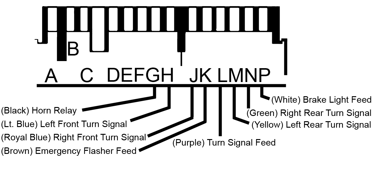 Source: ididitinc.com
So i was investigating some wiring stuff to do with my rear defroster on my 1998 sahara and came across the aftermarket wiring underneath the steering column, when i was checking the cluster. 1954 through 1959 beetles the ground circuit starts at the steering box to coupler joint which is grounded past the rubber steering coupler with a ground strap grounding out the metal steering shaft. The wiring arrangement is for a gm 4¼ connector. I went with the ez wiring harness, great product and every wire is labeled well all along the insulation. Do not wire this to the column.
 Source: pinterest.com
Wiring diagram includes numerous in depth illustrations that display the connection of varied items. The turn signal kit allows the electrical connection of vehicle harness wires to aftermarket, or factory gm steering column with either the 3 7/8 and 4 1/4 11 way turn signal and horn master connector. The other thing you will come across a circuit diagram could be lines. But, it doesn’t imply connection between the wires. A circuit is generally composed by various components.
 Source: wiringforums.com
In regards to the defroster, the problem ended up being a faulty timer, but i was curious about this accessory wiring. Left turn signal wiring diagram light blue (left front ts) yellow (left rear ts) green (right rear ts) 4 brown (hazards) not connected +12v, white (brake lts) always connected (controlled by brake pedal) +12v, purple (turn signal power) turn signal power (purple) connected to left side turn signals (light blue, yellow). Also the wiring diagram is in perspective as if you are looking at the plug from sitting in the seat, the left is pin 1 the right is pin 6. Connectors do not interchange and must be used in pairs. Do not wire this to the column.
 Source: nmielcarz.blogspot.com
3 wires bring 12v into the column; A circuit is generally composed by various components. I went with the ez wiring harness, great product and every wire is labeled well all along the insulation. I metered it out once i found the location of the ignition plug on the column, and it follows through the bulkhead connector to what i. Inside the gm tilt steering column page 5.
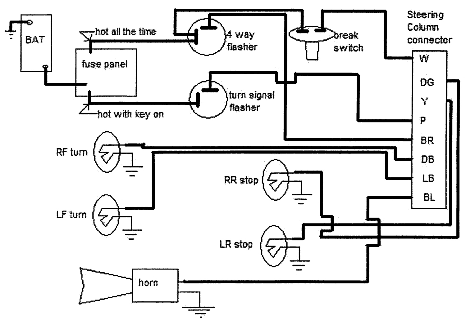 Source: wiringdiagram.2bitboer.com
I bought an aftermarket steering wheel and need to connect the horn. Wiring diagram includes numerous in depth illustrations that display the connection of varied items. Wiring up your new steering column can seem like a terrifying task. Do not wire this to the column. The special adapter allows the use of any steering column (or turn signal switch) and fits into the connector on the turn signal harness.
 Source: 2020cadillac.com
On the volute spring, the input wires are. I metered it out once i found the location of the ignition plug on the column, and it follows through the bulkhead connector to what i. Then slide the canceling cam over the column shaft and canceling cam spring.(figure b) 4. S4 is the horn button and k2 is the horn relay. On the volute spring, the input wires are.
 Source: costbindia.blogspot.com
S4 is the horn button and k2 is the horn relay. The turn signal kit allows the electrical connection of vehicle harness wires to aftermarket, or factory gm steering column with either the 3 7/8 and 4 1/4 11 way turn signal and horn master connector. The manual was pretty good at telling you what to wire to but still need to check. Also the wiring diagram is in perspective as if you are looking at the plug from sitting in the seat, the left is pin 1 the right is pin 6. Install the large 5/8”aluminum spacer over the column shaft.
 Source: wiringforums.com
On the volute spring, the input wires are. We start assembly with the core part, the column jacket assembly: On the volute spring, the input wires are. The one of the steering column cover and the exposed wires is not the ideal mounting location, i would. What the switch itself has is one yellow wire bringing power in for the horns, one green wire bringing power in from the brake light switch, one blue wire bringing power in from the flasher, one blue/yellow wire taking power out to the horns, one white/blue wire taking power out to the right front turn signal and right dash indicator, one green/white wire taking power out to.
This site is an open community for users to share their favorite wallpapers on the internet, all images or pictures in this website are for personal wallpaper use only, it is stricly prohibited to use this wallpaper for commercial purposes, if you are the author and find this image is shared without your permission, please kindly raise a DMCA report to Us.
If you find this site good, please support us by sharing this posts to your favorite social media accounts like Facebook, Instagram and so on or you can also save this blog page with the title aftermarket steering column wiring diagram by using Ctrl + D for devices a laptop with a Windows operating system or Command + D for laptops with an Apple operating system. If you use a smartphone, you can also use the drawer menu of the browser you are using. Whether it’s a Windows, Mac, iOS or Android operating system, you will still be able to bookmark this website.


