Your Accelerator pedal position sensor wiring diagram images are available. Accelerator pedal position sensor wiring diagram are a topic that is being searched for and liked by netizens now. You can Get the Accelerator pedal position sensor wiring diagram files here. Download all royalty-free images.
If you’re looking for accelerator pedal position sensor wiring diagram images information related to the accelerator pedal position sensor wiring diagram keyword, you have visit the right site. Our website frequently provides you with suggestions for seeking the highest quality video and picture content, please kindly hunt and find more informative video articles and graphics that fit your interests.
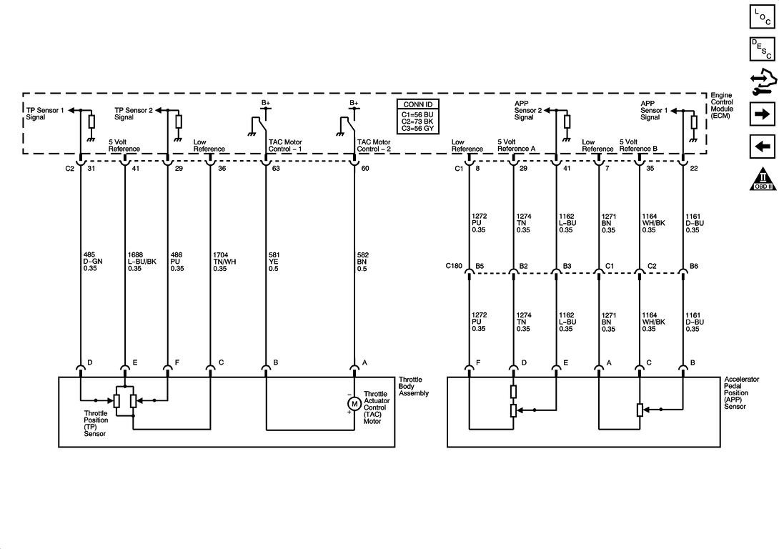
Accelerator Pedal Position Sensor Wiring Diagram. The app sensor is mounted on the accelerator pedal bracket and has 2 sensor circuits: If both are malfunctioning nothing will happen with the pedal. Accelerator pedal position sensor (sub) 78: Accelerator pedal position sensor wiring diagram wiring diagram is a simplified satisfactory pictorial representation of an electrical circuit it shows the components of the circuit as simplified shapes and the skill and signal links amongst the devices.
 Repair Guides Automatic Transaxle (2002) Dtc P1705 From autozone.com
This replaces the open/closed ivs switches in the old sensors. The accelerator pedal assembly is serviceable to the extent that the aps/ivs switch can be replaced without replacing the complete assembly. But if there is a problem with one sensor the pedal should still work but you will have warning indicators on. +b short in accelerator pedal position main sensor circuit. Accelerator pedal position sensor (sub) 78: G185 accelerator pedal position 2.
For example pin 1 of accelerator is.
Mounted on the accelerator pedal. Throttle actuator control motor ground: But, it doesn’t mean link between the cables. The cranks sensor should be a 2 pin inductive sensor that generates a voltage when the engine spins. That app sensor 1�s signal increases as the accelerator pedal is depressed, from below 1.1 volt at 0% pedal travel (pedal at rest) to above 2.1 volts at 100% pedal travel (pedal fully depressed). You’ll be in a position to understand specifically once the tasks ought to be completed, which makes it easier for you personally to effectively manage your time and.
 Source: volkswagenforum.co.uk
You’ll be in a position to understand specifically once the tasks ought to be completed, which makes it easier for you personally to effectively manage your time and. It includes directions and diagrams for various kinds of wiring methods as well as other items like lights, windows, and so forth. About press copyright contact us creators advertise developers terms privacy policy & safety how youtube works test new features press copyright contact us creators. Check power at the ecu side to confirm. The two main sources of input data are the accelerator pedal position sensors (app1 and app2) and throttle position sensors (tps).
 Source: 2020cadillac.com
Accelerator pedal position sensor wiring diagram wiring diagram is a simplified satisfactory pictorial representation of an electrical circuit it shows the components of the circuit as simplified shapes and the skill and signal links amongst the devices. The two main sources of input data are the accelerator pedal position sensors (app1 and app2) and throttle position sensors (tps). This is the repair procedure for the accelerator pedal position sensor. Check power at the ecu side to confirm. The app sensors 1 and 2 are integrated into one assembly located at the pedal assembly.
 Source: corvetteforum.com
In this example, the accelerator pedal position (app) sensor is of the potentiometer type. Power supply voltage applied to accelerator pedal position sensor (sub) 79: Throttle actuator control motor ground: But if there is a problem with one sensor the pedal should still work but you will have warning indicators on. Check voltage between app sensor.
 Source: wiringdatabaseinfo.blogspot.com
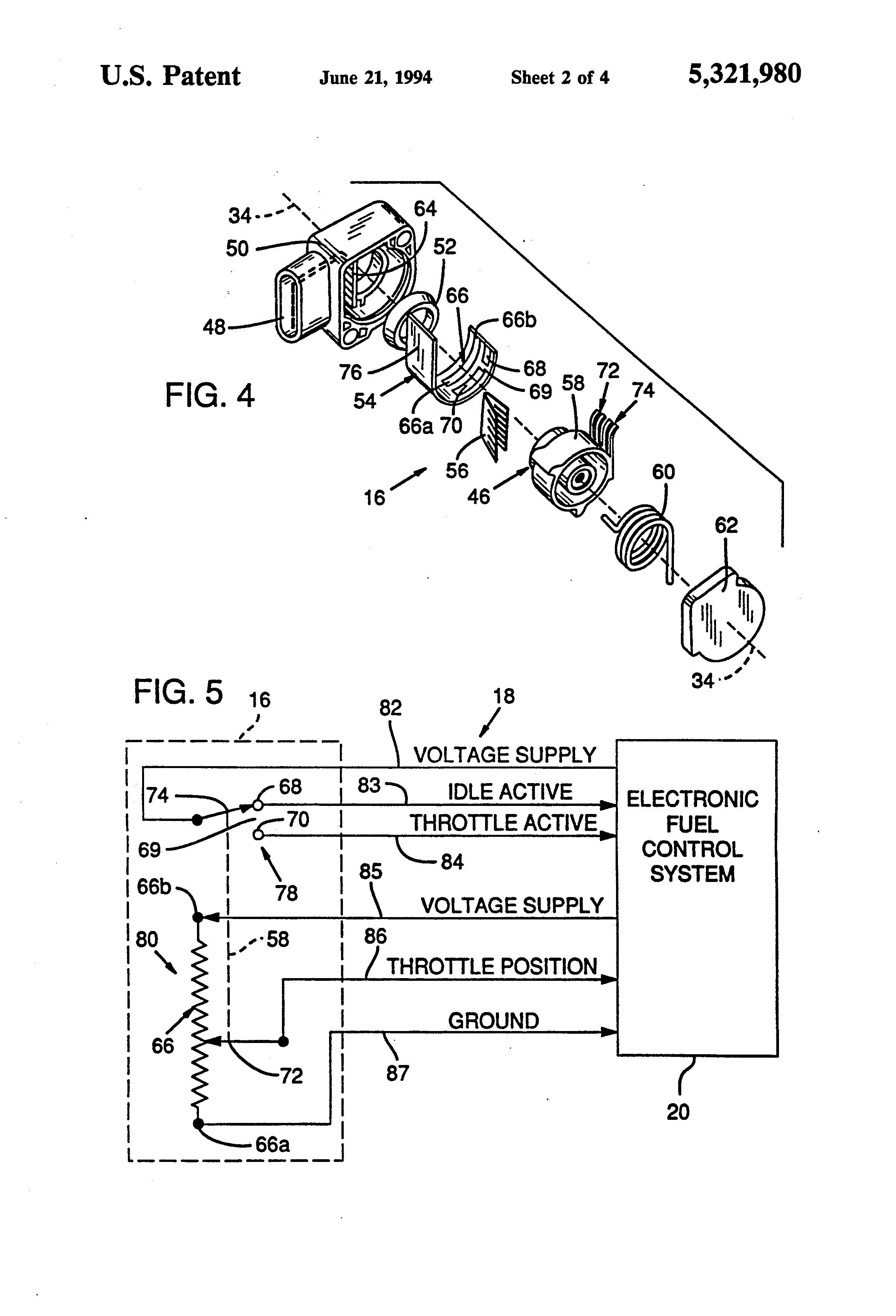
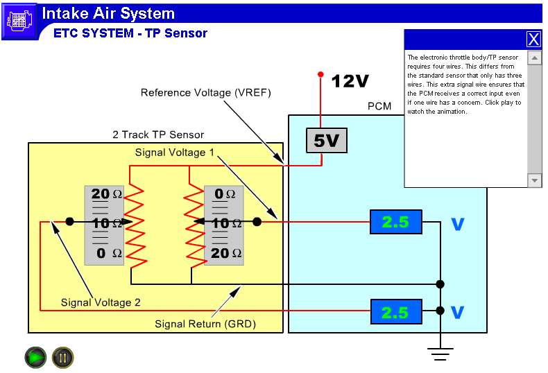
Check power at the ecu side to confirm. It receives two reference voltages from the powertrain control module (pcm), having two ground wires and two signal wires that send a varying voltage back to the pcm relating to accelerator pedal position. Discussion starter · #1 · apr 2, 2012. A potentiometer type throttle position sensor has three wires, a ground, voltage, and an output voltage (signal wire). The cranks sensor should be a 2 pin inductive sensor that generates a voltage when the engine spins.
 Source: powerstrokenation.com
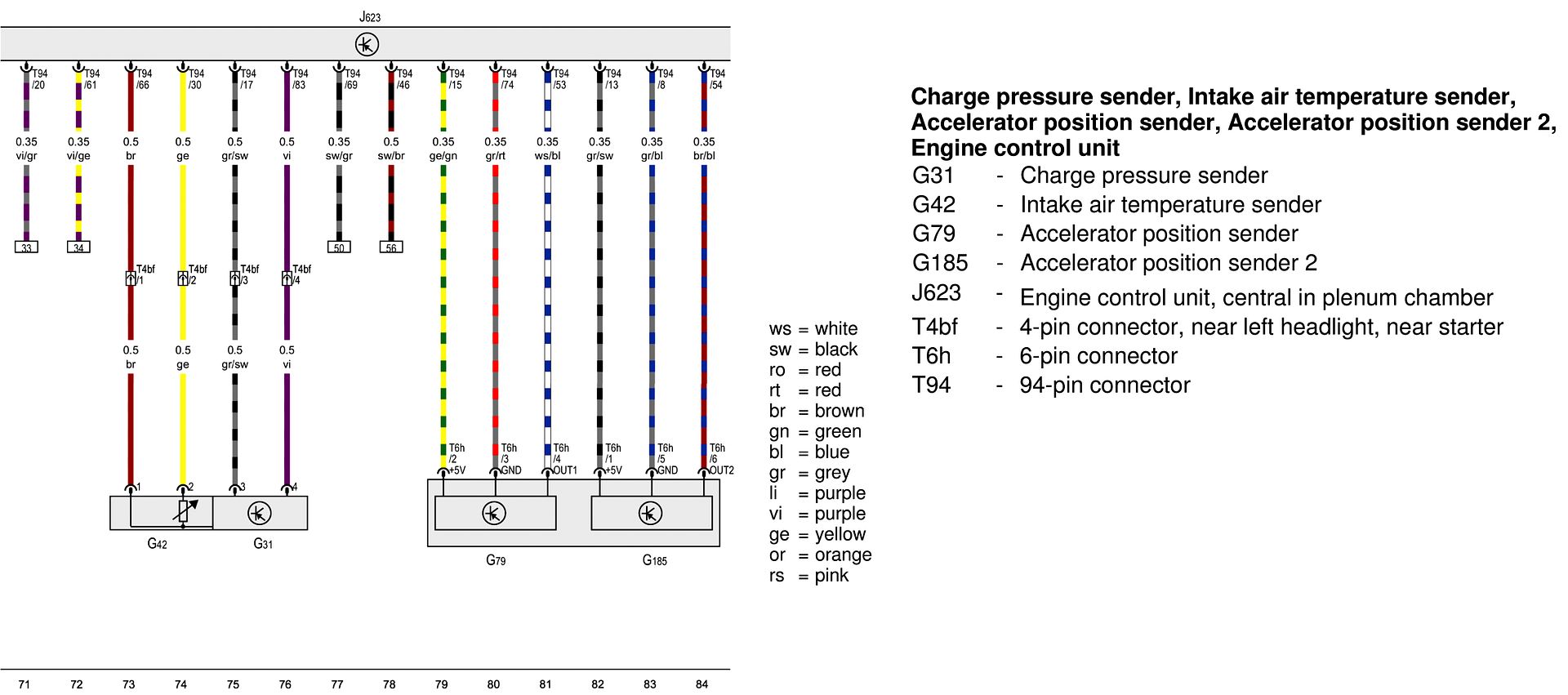
G185 accelerator pedal position 2. Accelerator pedal position sensor wiring diagram wiring diagram is a simplified satisfactory pictorial representation of an electrical circuit it shows the components of the circuit as simplified shapes and the skill and signal links amongst the devices. Accelerator pedal position sensor wiring diagram wiring diagram is a simplified satisfactory pictorial representation of an electrical circuit it shows the components of the circuit as simplified shapes and the skill and signal links amongst the devices. Accelerator pedal position sensor (main) ground: Test the throttle position sensor in a few minutes using a digital multimeter.
 Source: rx8club.com
Occasionally, the wires will cross. The cranks sensor should be a 2 pin inductive sensor that generates a voltage when the engine spins. Accelerator pedal position sensor (main) ground: +b short in accelerator pedal position main sensor circuit. The accelerator pedal position sensor has two potentiometers that act to validate pedal position.
 Source: 2020cadillac.com
Vpa (main) and vpa2 (sub). Check power at the ecu side to confirm. It has 2 sensor terminals (vpa and vpa2) to detect the accelerator pedal position and a malfunction. Ford car sensors and wiring diagram sensors and wiring diagram. Aps/ivs accelerator position signal in range dtc aps/ivs install the 5 wire breakout.
Source: support.haltech.com
Based on this information the load requested by the driver can be implemented immediately. The app sensors 1 and 2 are integrated into one assembly located at the pedal assembly. A potentiometer type throttle position sensor has three wires, a ground, voltage, and an output voltage (signal wire). Accelerator position sensor (aps) the ecm sends a regulated 5v signal through the ecm black chassis connector terminal 3 to aps connector terminal c. It has 2 sensor terminals (vpa and vpa2) to detect the accelerator pedal position and a malfunction.
 Source: autozone.com
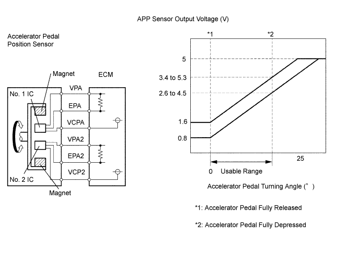
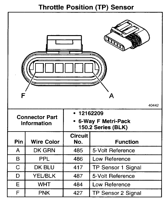
Examine the electrical connector wires and terminals for dirt, contamination. Each sensor has a 5 volt reference circuit, a low reference circuit, and a signal circuit. Vpa (main) and vpa2 (sub). +b short in accelerator pedal position main sensor circuit. The app sensor is mounted on the accelerator pedal bracket and has 2 sensor circuits:
 Source: kibodeclanchester.blogspot.com
The electronic throttle control (etc) system uses two accelerator pedal position (app) sensors to monitor the accelerator pedal position. So, a 6 pin accelerator pedal position sensor wiring diagram is, two wires are for the earth, two for the input voltage, and two for signals back to the computer (ecu). Accelerator pedal position sensor wiring diagram wiring diagram is a simplified satisfactory pictorial representation of an electrical circuit it shows the components of the circuit as simplified shapes and the skill and signal links amongst the devices. In this example, the accelerator pedal position (app) sensor is of the potentiometer type. Mounted on the accelerator pedal.
 Source: corvetteforum.com
This replaces the open/closed ivs switches in the old sensors. But, it doesn’t mean link between the cables. Each sensor has a 5 volt reference circuit, a low reference circuit, and a signal circuit. Power supply voltage applied to accelerator pedal position sensor (sub) 79: But if there is a problem with one sensor the pedal should still work but you will have warning indicators on.
 Source: dentistmitcham.com
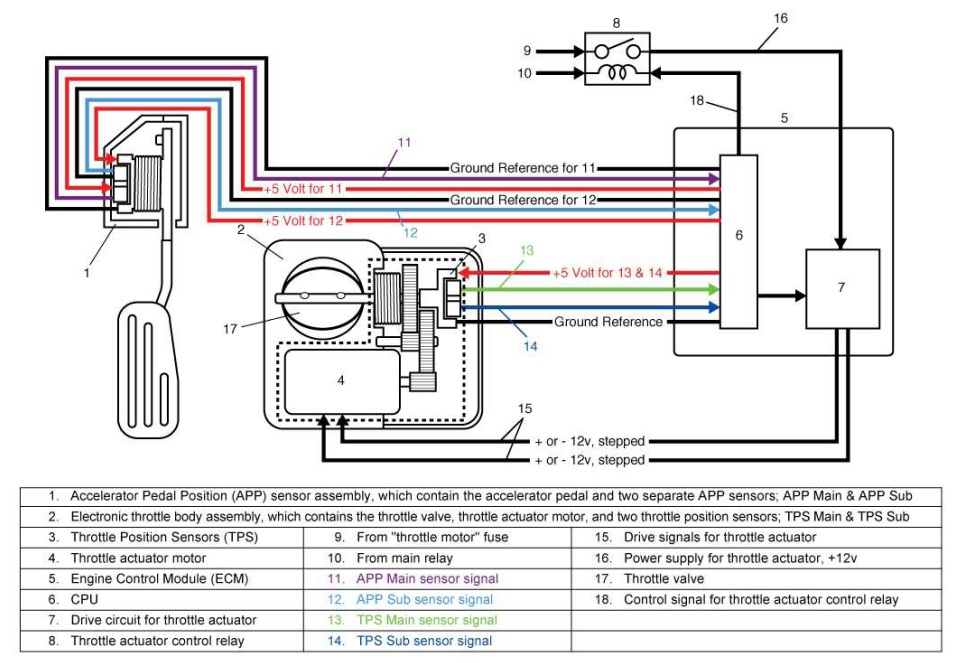
Idle position of the accelerator pedal is determined by the ecm receiving the signal from the accelerator pedal position sensor. It has 2 sensor terminals (vpa and vpa2) to detect the accelerator pedal position and a malfunction. As a result of this new design, the It receives two reference voltages from the powertrain control module (pcm), having two ground wires and two signal wires that send a varying voltage back to the pcm relating to accelerator pedal position. Injunction of 2 wires is usually indicated by black dot in the junction of 2 lines.
 Source: rx8club.com
Accelerator pedal position sensor wiring diagram wiring diagram is a simplified satisfactory pictorial representation of an electrical circuit it shows the components of the circuit as simplified shapes and the skill and signal links amongst the devices. Aps/ivs accelerator position signal in range dtc aps/ivs install the 5 wire breakout. Both sensors are in the accelerator. Ford car sensors and wiring diagram sensors and wiring diagram. The cam sensor is a hall effect sensor and will have a voltage from the ecu @ 5v like you say.
Source: wiringdiagrammechanic.blogspot.com
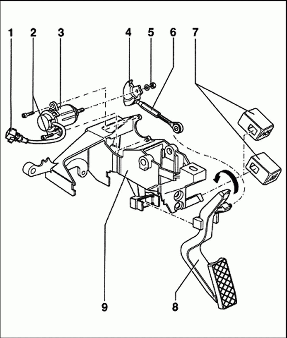
That the accelerator pedal assembly is made up of 3 individual position sensors. Trying to replace the accel pedal sensor on my 01 ex 7.3l to accomodate a tuner. Ford car sensors and wiring diagram sensors and wiring diagram. It includes directions and diagrams for various kinds of wiring methods as well as other items like lights, windows, and so forth. You’ll be in a position to understand specifically once the tasks ought to be completed, which makes it easier for you personally to effectively manage your time and.
 Source: 2020cadillac.com
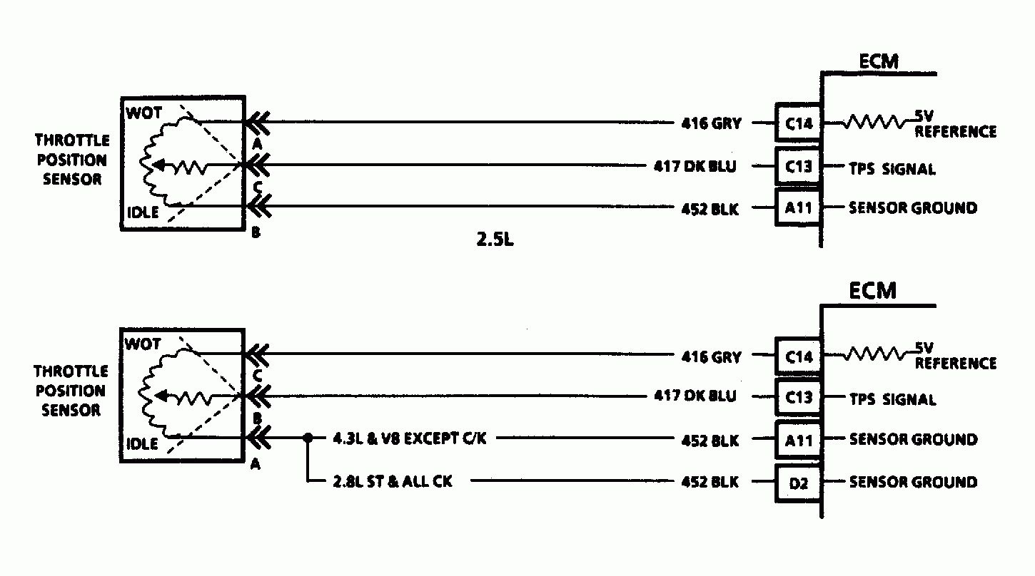
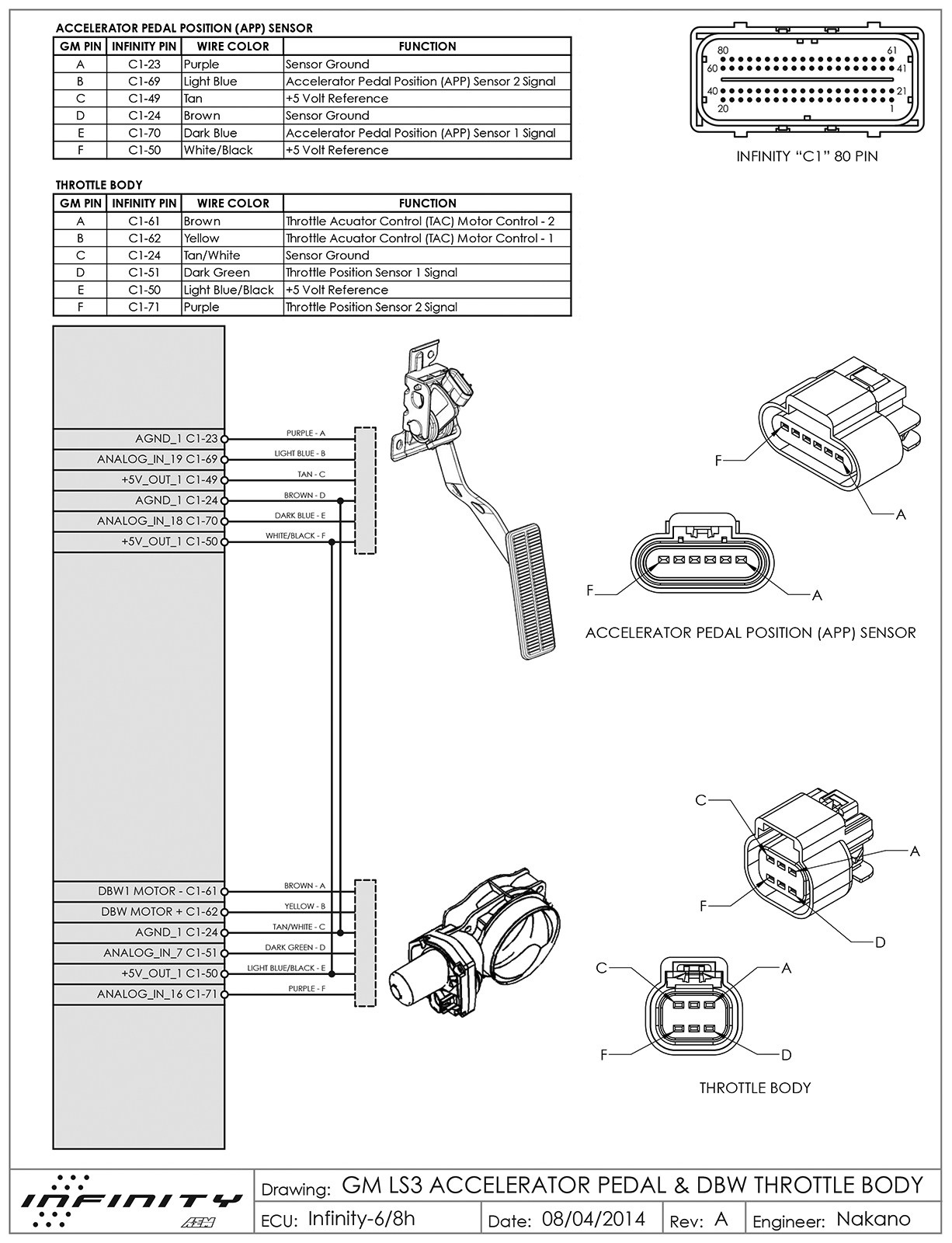
A potentiometer type throttle position sensor has three wires, a ground, voltage, and an output voltage (signal wire). As a result of this new design, the The app sensor is mounted on the accelerator pedal bracket and has 2 sensor circuits: The driver’s perception of acceleration with properly operating electronic throttle control (etc) is virtually the same as it would be if there was a throttle cable connected from the pedal to the throttle body plate. This is the repair procedure for the accelerator pedal position sensor.
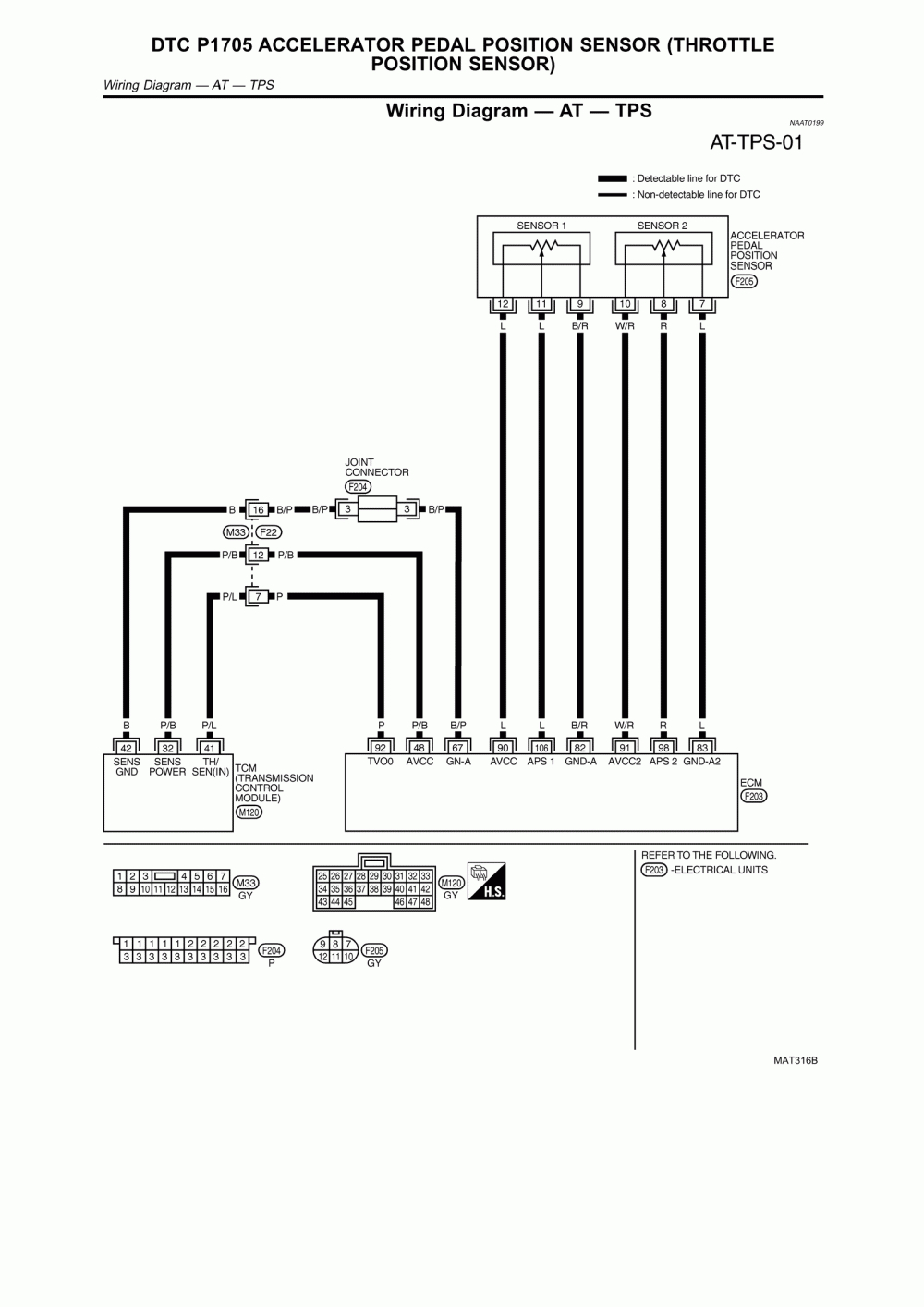 Source: 2020cadillac.com
Discussion starter · #1 · apr 2, 2012. +b short in accelerator pedal position main sensor circuit. As a result of this new design, the The cam sensor is a hall effect sensor and will have a voltage from the ecu @ 5v like you say. Occasionally, the wires will cross.
 Source: autozone.com
The accelerator pedal assembly is serviceable to the extent that the aps/ivs switch can be replaced without replacing the complete assembly. But, it doesn’t mean link between the cables. The accelerator pedal assembly is serviceable to the extent that the aps/ivs switch can be replaced without replacing the complete assembly. In this example, the accelerator pedal position (app) sensor is of the potentiometer type. Each sensor has a 5 volt reference circuit, a low reference circuit, and a signal circuit.
 Source: autozone.com
It receives two reference voltages from the powertrain control module (pcm), having two ground wires and two signal wires that send a varying voltage back to the pcm relating to accelerator pedal position. +b short in accelerator pedal position main sensor circuit. Discussion starter · #1 · apr 2, 2012. But, it doesn’t mean link between the cables. Power supply voltage applied to accelerator pedal position sensor (sub) 79:
This site is an open community for users to share their favorite wallpapers on the internet, all images or pictures in this website are for personal wallpaper use only, it is stricly prohibited to use this wallpaper for commercial purposes, if you are the author and find this image is shared without your permission, please kindly raise a DMCA report to Us.
If you find this site serviceableness, please support us by sharing this posts to your preference social media accounts like Facebook, Instagram and so on or you can also save this blog page with the title accelerator pedal position sensor wiring diagram by using Ctrl + D for devices a laptop with a Windows operating system or Command + D for laptops with an Apple operating system. If you use a smartphone, you can also use the drawer menu of the browser you are using. Whether it’s a Windows, Mac, iOS or Android operating system, you will still be able to bookmark this website.


