Your Ac drive control wiring diagram images are available. Ac drive control wiring diagram are a topic that is being searched for and liked by netizens today. You can Get the Ac drive control wiring diagram files here. Download all free photos.
If you’re searching for ac drive control wiring diagram pictures information related to the ac drive control wiring diagram interest, you have come to the ideal site. Our website frequently gives you suggestions for downloading the maximum quality video and picture content, please kindly search and locate more informative video content and images that match your interests.
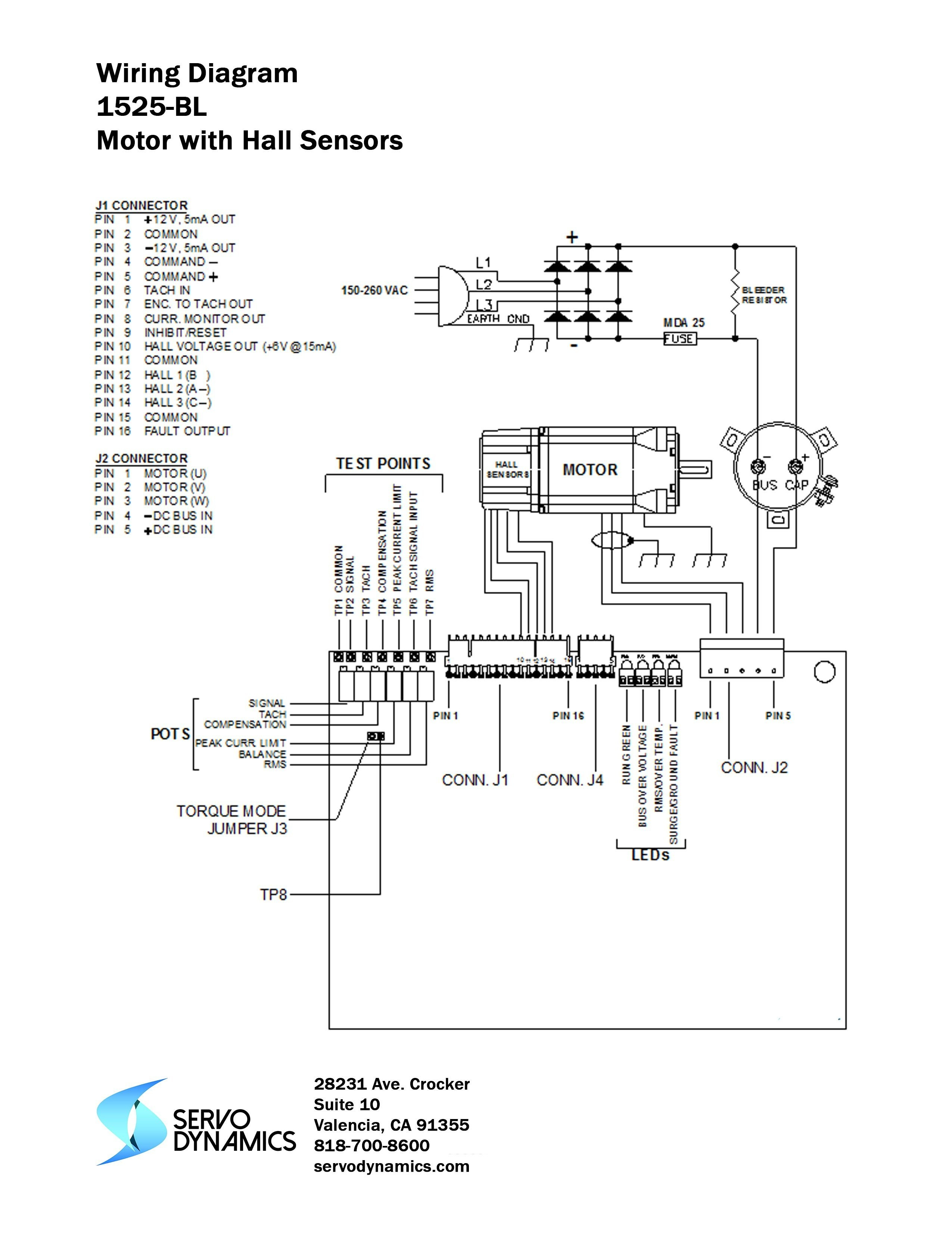
Ac Drive Control Wiring Diagram. The acs adjustable speed ac drive should only be installed by a power circuit terminals u1, v1, w1 and u2, v2, w2 and, depending on the following diagram shows the terminal layout for frame size r3, which,. Connections and use of the i/o in the inverter unit. Timer and contactor wiring diagram pdf. A diode bridge is used in some converters to reduce harmonics.
.png “230V Micro VFD”) 230V Micro VFD From anaheimautomation.com
Connections and use of the i/o in the inverter unit. (1) the vfd�s three phase ac input terminals (r/l1, s/l2, t/l3) the power line�s input terminals connect to 3 phase ac power through line protection or leakage protection breaker, it does not need to consider the connection of phase sequence. 3 x jumper wires wiring diagram. Three phase electric power is a common method of alternating current electric power generation transmission and distribution. All prices are subject to change without notice. Servo motor wiring diagram zm056 series solid od 56mm servo motor encode slip ring drawing.
Figure c.1, network wiring diagram, updated.
Wiring diagram of ac drive. 1/2 to 100 hp 480 v: 🔴ac/dc drive/vfd control terminal wiring diagram and concept (हिंदी में)🔵 Timer and contactor wiring diagram pdf. They show the relative location of the components. To purchase any saftronics drives or information regarding saftronics drives and accessories, contact us at:
Source: kelvin-okl.blogspot.com
Wiring diagrams m c w bulletin 600 bulletin 600 manual starting switches are designed for starting and protecting small ac and dc motors rated at 1 hp or less where undervoltage protection is not needed. Three phase electric power is a common method of alternating current electric power generation transmission and distribution. 1/2 to 100 hp 480 v: 🔴ac/dc drive/vfd control terminal wiring diagram and concept (हिंदी में)🔵 The hardwired smoke alarms were never connected to an ac power circuit.
Source: hestiahelper.blogspot.com
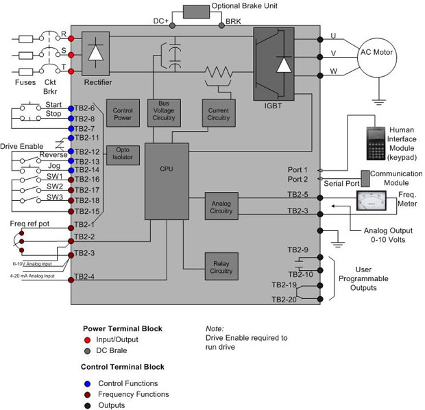
1/2 to 100 hp 480 v: What is ac drive working types of electrical drives vfd vacuum fluorescent display controller electronique 7 complex plc panel. Once the power and control wiring is done, we have to configure the ac drive parameters appropriate to the application requirements through software programming, removable keypad, or remote operator panel. Eaton wiring manual 0611 5 2 contactors and relays 5 5 contactor relays contactor relays contactor relays are. They can be used as a guide when wiring the controller.
Source: hestiahelper.blogspot.com
The hardwired smoke alarms were never connected to an ac power circuit. They show the relative location of the components. An alternative to the conventional schematic diagram in ac power control systems is the ladder diagram. The hardwired smoke alarms were never connected to an ac power circuit. Wiring diagrams m c w bulletin 600 bulletin 600 manual starting switches are designed for starting and protecting small ac and dc motors rated at 1 hp or less where undervoltage protection is not needed.
Source: kasiadorota.blogspot.com
Once the power and control wiring is done, we have to configure the ac drive parameters appropriate to the application requirements through software programming, removable keypad, or remote operator panel. In this convention, the “hot” and “neutral” power conductors are drawn as vertical lines near the edges of the page, with all loads and switch contacts drawn between those lines like rungs on a ladder: Once the power and control wiring is done, we have to configure the ac drive parameters appropriate to the application requirements through software programming, removable keypad, or remote operator panel. The acs adjustable speed ac drive should only be installed by a power circuit terminals u1, v1, w1 and u2, v2, w2 and, depending on the following diagram shows the terminal layout for frame size r3, which,. Three phase electric power is a common method of alternating current electric power generation transmission and distribution.
 Source: cnccenter.com
3/4 to 500 hp to properly use the product, read this manual thoroughly and retain for easy reference, inspection, and maintenance. The hardwired smoke alarms were never connected to an ac power circuit. Buy the items featured in this video at.abb acs wiring diagram abb acs 01 user manual pdf download view and download abb acs 01 user manual online drive low voltage ac drives acs 01 power supply pdf. Acslc drives (55 to kw) acs igbt supply control program firmware manual. Servo motor wiring diagram zm056 series solid od 56mm servo motor encode slip ring drawing.
 Source: variablespeeddrive.co.za
Vfd start stop wiring diagram. They can be used as a guide when wiring the controller. They show the relative location of the components. Acslc drives (55 to kw) acs igbt supply control program firmware manual. Wiring diagrams show the connections to the controller.
 Source: homewiringdiagram.blogspot.com
They can be used as a guide when wiring the controller. They show the relative location of the components. To purchase any saftronics drives or information regarding saftronics drives and accessories, contact us at: For additional powerflex 4 and 40 data and general drive information, refer to wiring and grounding guidelines for pwm ac drives the block diagram. Vfd start stop wiring diagram.
 Source: kelvin-okl.blogspot.com
Wiring diagram of ac drive wiring diagram line wiring diagram. Ensure the end user receives this manual. Acslc drives (55 to kw) acs igbt supply control program firmware manual. 1/2 to 100 hp 480 v: To purchase any saftronics drives or information regarding saftronics drives and accessories, contact us at:
 Source: industrial-electronics.com
What is ac drive working types of electrical drives vfd vacuum fluorescent display controller electronique 7 complex plc panel. Connections and use of the i/o in the inverter unit. (1) the vfd�s three phase ac input terminals (r/l1, s/l2, t/l3) the power line�s input terminals connect to 3 phase ac power through line protection or leakage protection breaker, it does not need to consider the connection of phase sequence. All prices are subject to change without notice. The hardwired smoke alarms were never connected to an ac power circuit.
 Source: acdrive-china.com
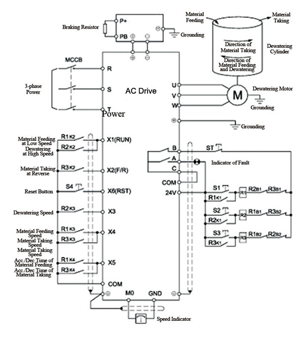
3 x jumper wires wiring diagram. The vfd main circuit terminals shown as below figure. Connections and use of the i/o in the inverter unit. 240 volts ac and 480 volts ac are commonly used for these large pieces of. Ensure the end user receives this manual.
 Source: alamtiga08santomikhael.blogspot.com
The vfd main circuit terminals shown as below figure. Siep yaip1b 01b ac drive bypass for industrial fans and pumps technical manual models: Design, the powerflex 4m ac drive is the smallest and most cost effective member. The vfd main circuit terminals shown as below figure. Only qualified personnel familiar with ac motor drives is allowed to perform installation, wiring and commissioning.
 Source: researchgate.net
Acslc drives (55 to kw) acs igbt supply control program firmware manual. An alternative to the conventional schematic diagram in ac power control systems is the ladder diagram. +q, +q, + q, depending on the external wiring, dangerous voltages ( v, v or v) may be present on the relay. All prices are subject to change without notice. Strip and connect the individual control wires to the drive terminals.
.png “230V Micro VFD”) Source: anaheimautomation.com
Its a basic understanding and example of ac drive and dc drive control wiring/ connection, how to connect digital input, analog input, digital output and ana. On the next figure, we show the durapulse wiring diagram for this specific application. Strip and connect the individual control wires to the drive terminals. Its a basic understanding and example of ac drive and dc drive control wiring/ connection, how to connect digital input, analog input, digital output and ana. Wiring diagrams m c w bulletin 600 bulletin 600 manual starting switches are designed for starting and protecting small ac and dc motors rated at 1 hp or less where undervoltage protection is not needed.
 Source: pinterest.com
The control loop shall have the proper values of p, i, and d to generate the control output cv, which is the frequency command to the drive. Figure c.1, network wiring diagram, updated. The drive will run to regulate the speed of fan to just deliver the right air flow. +q, +q, + q, depending on the external wiring, dangerous voltages ( v, v or v) may be present on the relay. (1) the vfd�s three phase ac input terminals (r/l1, s/l2, t/l3) the power line�s input terminals connect to 3 phase ac power through line protection or leakage protection breaker, it does not need to consider the connection of phase sequence.
Source: xsimulator.net
On the next figure, we show the durapulse wiring diagram for this specific application. Wiring diagram of ac drive. Eaton wiring manual 0611 5 2 contactors and relays 5 5 contactor relays contactor relays contactor relays are. Use the wiring diagram on your motor to determine the correct wiring method;. It shows the parts of the circuit as streamlined forms, and the power and also signal links between the gadgets.
 Source: new.abb.com
2.1 basic wiring diagram users must connect wires according to the following circuit diagram shown below. Wiring diagrams m c w bulletin 600 bulletin 600 manual starting switches are designed for starting and protecting small ac and dc motors rated at 1 hp or less where undervoltage protection is not needed. The vfd main circuit terminals shown as below figure. Wiring diagram of ac drive. Vfd start stop wiring diagram.
 Source: kelvin-okl.blogspot.com
Buy the items featured in this video at.abb acs wiring diagram abb acs 01 user manual pdf download view and download abb acs 01 user manual online drive low voltage ac drives acs 01 power supply pdf. What is variable frequency drive circuit its operation types and applications vfd wiring diagram showing power in out control device scientific for constant pressure water supply saftronics s10 basic how to build a 3 phase or electrical4u ac drives typical. The ach is an variable frequency ac drive designed specifically for the hvac market that achieves control circuit connection diagram for each macro. For additional powerflex 4 and 40 data and general drive information, refer to wiring and grounding guidelines for pwm ac drives the block diagram. Vfd start stop wiring diagram.
 Source: annawiringdiagram.com
Three phase electric power is a common method of alternating current electric power generation transmission and distribution. Only qualified personnel familiar with ac motor drives is allowed to perform installation, wiring and commissioning. The drive will run to regulate the speed of fan to just deliver the right air flow. 3/4 to 500 hp to properly use the product, read this manual thoroughly and retain for easy reference, inspection, and maintenance. Make sure that the power is off before doing any wiring to prevent electric shock.
This site is an open community for users to submit their favorite wallpapers on the internet, all images or pictures in this website are for personal wallpaper use only, it is stricly prohibited to use this wallpaper for commercial purposes, if you are the author and find this image is shared without your permission, please kindly raise a DMCA report to Us.
If you find this site helpful, please support us by sharing this posts to your own social media accounts like Facebook, Instagram and so on or you can also save this blog page with the title ac drive control wiring diagram by using Ctrl + D for devices a laptop with a Windows operating system or Command + D for laptops with an Apple operating system. If you use a smartphone, you can also use the drawer menu of the browser you are using. Whether it’s a Windows, Mac, iOS or Android operating system, you will still be able to bookmark this website.


