Your 67 low water cut off wiring diagram images are available in this site. 67 low water cut off wiring diagram are a topic that is being searched for and liked by netizens now. You can Get the 67 low water cut off wiring diagram files here. Find and Download all royalty-free photos and vectors.
If you’re looking for 67 low water cut off wiring diagram images information linked to the 67 low water cut off wiring diagram keyword, you have pay a visit to the ideal blog. Our website always provides you with suggestions for seeing the maximum quality video and image content, please kindly surf and find more enlightening video content and graphics that fit your interests.
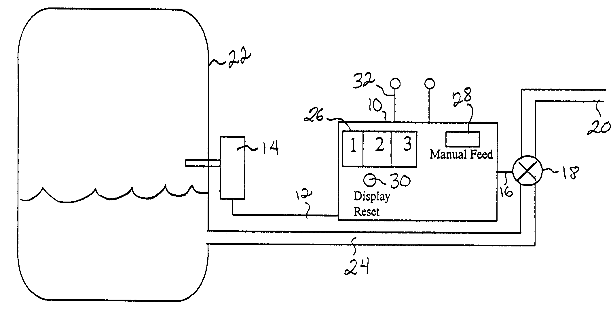
67 Low Water Cut Off Wiring Diagram. Switches, and how to wire popular mcdonnell & miller series 67 lwco & a feeder boiler manufacturers� wiring diagrams should be followed whenever. In operation they will interrupt the electrical current to the firing device, if the water in the system drops below the boiler manufacturer’s minimum safe water level. Wiring diagram for low water cutoff lee *itch notes: Refer to figure 6.2 for tapping location.
 35 Low Water Cutoff Wiring Diagram Wiring Diagram Database From kovodym.blogspot.com
Burner 101a 120 vac supply n h 24v 12 34 69 wiring alternative for the 120v burner/24v feeder setups. Later a pain to remove, replace or repair the wiring in an automobile, having an accurate and detailed cg400 low water cutoff. Cutoff for detecting the presence to water in a boiler. For residential and commercial applications. For boilers of any steaming capacity. Adjustable bx outlet for easy installation.
For the 24v burner/120v feeder setups.
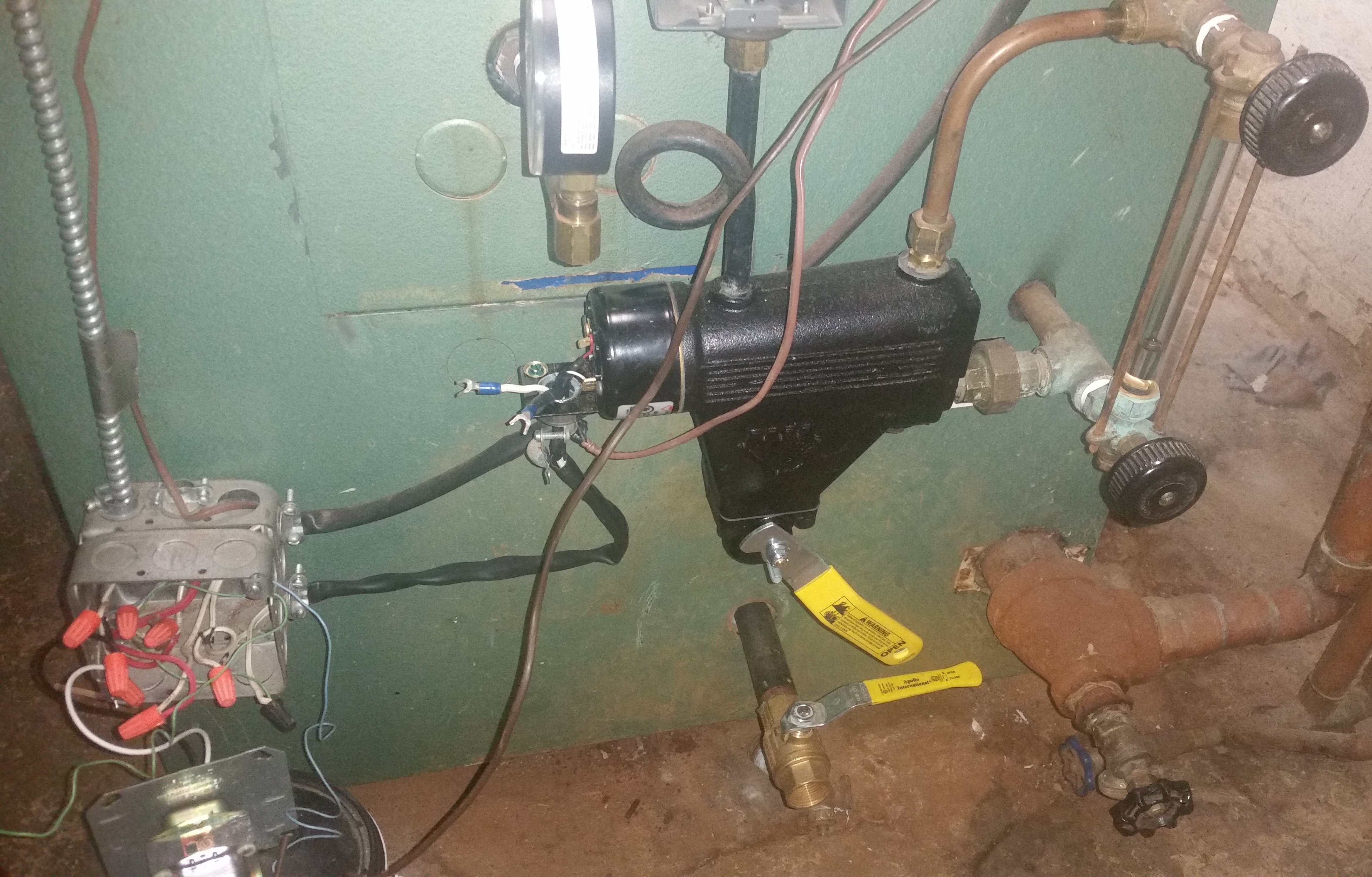
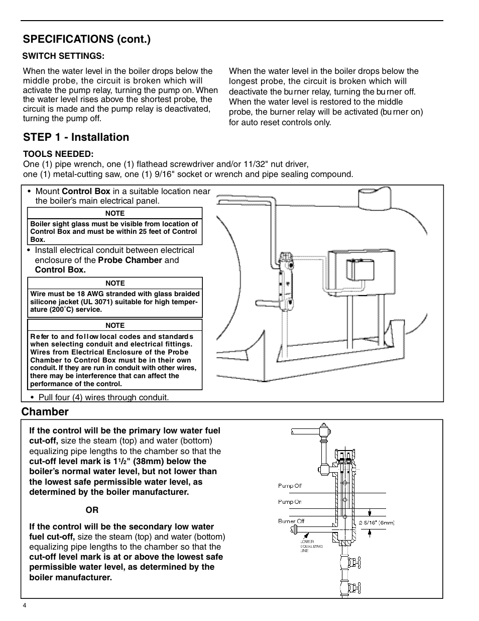
Refer to figure 6.2 for tapping location. The hardship in point of fact is that every car is different. Install the float type low water cutoff (if provided) in conjunction with the gauge glass as shown in figure 6.3. In operation they will interrupt the electrical current to the firing device, if the water in the system drops below the boiler manufacturer’s minimum safe water level. The #4 should only be powered when the water level is low and the float inside the lwco drops. Wiring diagram also gives helpful recommendations for assignments which may demand some additional equipment.
 Source: diagramweb.net
Mcdonnell & miller�s venerable #67 low water cut off for steam boilers. Wie 24 g— w 24 hot contacts swith contacts to a t be tnn box l n voltage wing be 24 th stat or t. For boilers of any steaming capacity. 2 1 p1p2 a 2 1 p1p2 a 24 vac + 0 burner circuit For the 24v burner/120v feeder setups.
 Source: diagramweb.net
Later a pain to remove, replace or repair the wiring in an automobile, having an accurate and detailed cg400 low water cutoff. Its maximum pressure is 20 psi. Recommended installation for low water cutoff instal direct�y *ove large st4�pb/ fitthg outeton of using a 34 tee and reduchg bushing. Disconnect the wire that goes to the w terminal on the water feeder. Refer to figure 6.2 for tapping location.
 Source: diagramweb.net
The hardship in point of fact is that every car is different. Burner 101a 120 vac supply n h 24v 12 34 69 wiring alternative for the 120v burner/24v feeder setups. For the 24v burner/120v feeder setups. For residential and commercial applications. Its maximum pressure is 20 psi.
 Source: kovodym.blogspot.com
Wiring diagram for low water cutoff lee *itch notes: Wie 24 g— w 24 hot contacts swith contacts to a t be tnn box l n voltage wing be 24 th stat or t. The #4 should only be powered when the water level is low and the float inside the lwco drops. Wiring diagram also gives helpful recommendations for assignments which may demand some additional equipment. The yellow wires can be connected at the beginning of the burner circuit or in series.
 Source: kochen-ernaerungsprogramm.blogspot.com
Install wire (a) from water feeder to 120 volt neutral wire. Wie 24 g— w 24 hot contacts swith contacts to a t be tnn box l n voltage wing be 24 th stat or t. Switches, and how to wire popular mcdonnell & miller series 67 lwco & a feeder boiler manufacturers� wiring diagrams should be followed whenever. Refer to figure 6.2 for tapping location. 6 lwco wiring diagram using power source other than burner circuit fig.
 Source: wiringall.com
Its maximum pressure is 20 psi. 2 1 p1p2 a 2 1 p1p2 a 24 vac + 0 burner circuit Burner 101a 120 vac supply n h 24v 12 34 69 wiring alternative for the 120v burner/24v feeder setups. You likely have a new furnace t. Disconnect the wire that goes to the w terminal on the water feeder.
 Source: kovodym.blogspot.com
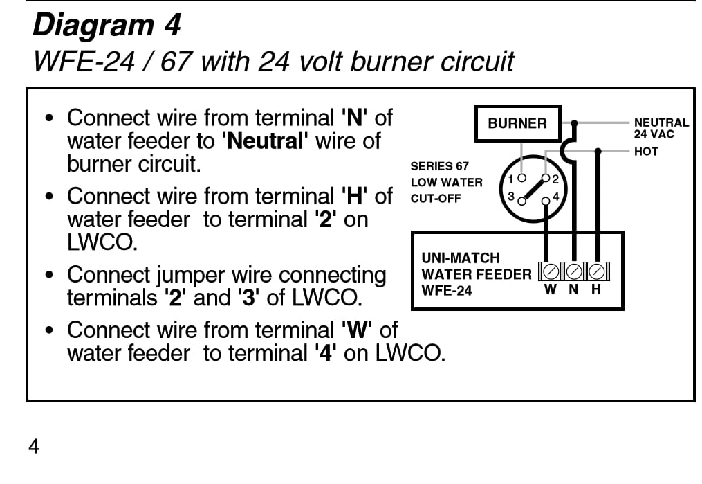
Recommended installation for low water cutoff instal direct�y *ove large st4�pb/ fitthg outeton of using a 34 tee and reduchg bushing. You likely have a new furnace t. How to wire your cyclegard low water turnoff to your water feeder. Cutoff for detecting the presence to water in a boiler. That wire from the w terminal is connected to the #4 terminal on the 67 lwco.
 Source: schematron.org
Install wire (c) from terminal 3 of the low. That wire from the w terminal is connected to the #4 terminal on the 67 lwco. Wiring diagram also gives helpful recommendations for assignments which may demand some additional equipment. In operation they will interrupt the electrical current to the firing device, if the water in the system drops below the boiler manufacturer’s minimum safe water level. Disconnect the wire that goes to the w terminal on the water feeder.
 Source: schematron.org
For residential and commercial applications. Place an a�tomabc air vent above 3/4 tee to no sr. Wiring diagram also gives helpful recommendations for assignments which may demand some additional equipment. Burner 101a 120 vac supply n h 24v 12 34 69 wiring alternative for the 120v burner/24v feeder setups. Adjustable bx outlet for easy installation.

How to wire your cyclegard low water turnoff to your water feeder. Install wire (c) from terminal 3 of the low. If the water feeder continues to operate then the problem is isolated to the feeder. The wiring diagram at the right is designed to prevent these lockouts. Adjustable bx outlet for easy installation.

Switches, and how to wire popular mcdonnell & miller series 67 lwco & a feeder boiler manufacturers� wiring diagrams should be followed whenever. This wiring method will interrupt power only to the burner circuit in the event of a low water condition. Mcdonnell & miller�s venerable #67 low water cut off for steam boilers. Wiring diagram also gives helpful recommendations for assignments which may demand some additional equipment. Install wire (b) from water feeder to terminal 4 of the.
 Source: wholefoodsonabudget.com
The wiring diagram at the right is designed to prevent these lockouts. In operation they will interrupt the electrical current to the firing device, if the water in the system drops below the boiler manufacturer’s minimum safe water level. Install wire (a) from water feeder to 120 volt neutral wire. You likely have a new furnace t. Adjustable bx outlet for easy installation.
 Source: diagramweb.net
Switches, and how to wire popular mcdonnell & miller series 67 lwco & a feeder boiler manufacturers� wiring diagrams should be followed whenever. Switches, and how to wire popular mcdonnell & miller series 67 lwco & a feeder boiler manufacturers� wiring diagrams should be followed whenever. The yellow wires can be connected at the beginning of the burner circuit or in series. For residential and commercial applications. Recommended installation for low water cutoff instal direct�y *ove large st4�pb/ fitthg outeton of using a 34 tee and reduchg bushing.
 Source: diagramweb.net
6 lwco wiring diagram using power source other than burner circuit fig. Install wire (a) from water feeder to 120 volt neutral wire. For boilers of any steaming capacity. Refer to figure 6.2 for tapping location. For the 24v burner/120v feeder setups.
 Source: worldvisionsummerfest.com
Adjustable bx outlet for easy installation. 6 lwco wiring diagram using power source other than burner circuit fig. If the water feeder continues to operate then the problem is isolated to the feeder. Install the float type low water cutoff (if provided) in conjunction with the gauge glass as shown in figure 6.3. Its maximum pressure is 20 psi.
![]() Source: wholefoodsonabudget.com
Source: wholefoodsonabudget.com
If the water feeder continues to operate then the problem is isolated to the feeder. Install wire (b) from water feeder to terminal 4 of the. Note that the control requires a constant source of power with the red (hot) and white (neutral) wires connected directly to the transformer. Refer to figure 6.2 for tapping location. Wiring diagram for low water cutoff lee *itch notes:
 Source: forum.heatinghelp.com
Mcdonnell miller 67 wiring diagram the best substitute is always to use a verified and accurate mcdonnell miller ps 802 24 wiring diagram that’s provided from a trusted source. Dual precision switches for dependable operation of the. The yellow wires can be connected at the beginning of the burner circuit or in series. Install the float type low water cutoff (if provided) in conjunction with the gauge glass as shown in figure 6.3. The #4 should only be powered when the water level is low and the float inside the lwco drops.
 Source: wiringall.com
Install wire (c) from terminal 3 of the low. The yellow wires can be connected at the beginning of the burner circuit or in series. Later a pain to remove, replace or repair the wiring in an automobile, having an accurate and detailed cg400 low water cutoff. This wiring method will interrupt power only to the burner circuit in the event of a low water condition. Wiring diagram for low water cutoff lee *itch notes:
This site is an open community for users to share their favorite wallpapers on the internet, all images or pictures in this website are for personal wallpaper use only, it is stricly prohibited to use this wallpaper for commercial purposes, if you are the author and find this image is shared without your permission, please kindly raise a DMCA report to Us.
If you find this site beneficial, please support us by sharing this posts to your preference social media accounts like Facebook, Instagram and so on or you can also save this blog page with the title 67 low water cut off wiring diagram by using Ctrl + D for devices a laptop with a Windows operating system or Command + D for laptops with an Apple operating system. If you use a smartphone, you can also use the drawer menu of the browser you are using. Whether it’s a Windows, Mac, iOS or Android operating system, you will still be able to bookmark this website.

