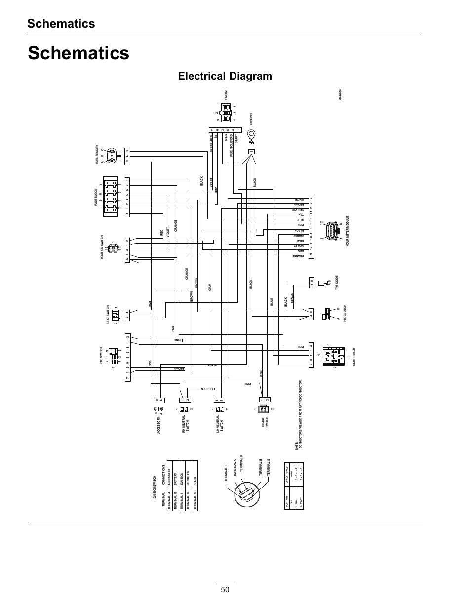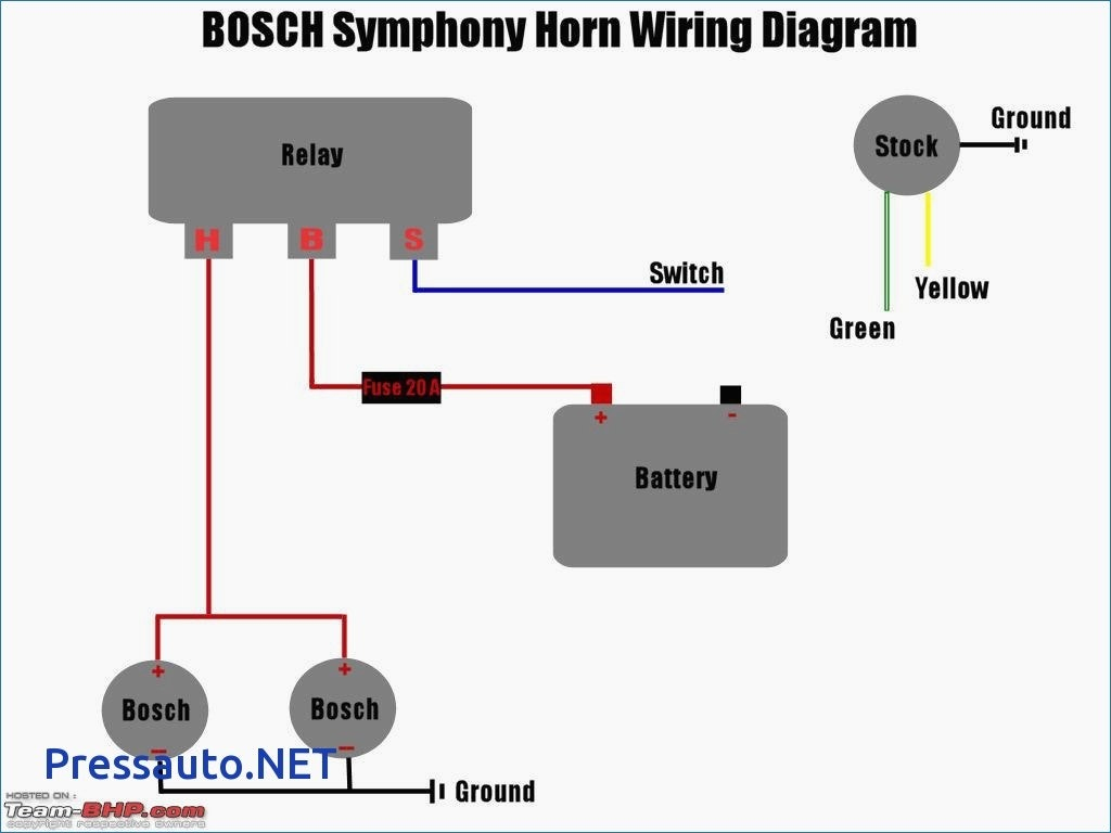
Your 5 wire o2 sensor wiring diagram images are available. 5 wire o2 sensor wiring diagram are a topic that is being searched for and liked by netizens now. You can Get the 5 wire o2 sensor wiring diagram files here. Find and Download all free images.
If you’re searching for 5 wire o2 sensor wiring diagram images information linked to the 5 wire o2 sensor wiring diagram topic, you have pay a visit to the right site. Our site frequently provides you with hints for seeking the highest quality video and image content, please kindly surf and locate more enlightening video articles and images that fit your interests.
5 Wire O2 Sensor Wiring Diagram. A wiring diagram usually gives assistance just. Open the bonnet of the vehicle and locate the o2 sensor. Bosch oxygen sensor 16123 the home depot in 2021 sensors technology. The first component is symbol that indicate electric element in the circuit.
![[DIAGRAM] 3 Wire O2 Sensor Wiring Diagram FULL Version HD [DIAGRAM] 3 Wire O2 Sensor Wiring Diagram FULL Version HD](https://ww2.justanswer.com/uploads/baddad1/2011-02-24_141910_capture.png) [DIAGRAM] 3 Wire O2 Sensor Wiring Diagram FULL Version HD From webflowdiagrams.bumbleweb.fr
[DIAGRAM] 3 Wire O2 Sensor Wiring Diagram FULL Version HD From webflowdiagrams.bumbleweb.fr
O2 sensor wiring diagram.this little pic is the wire side of the primary o2 sensor plug. This is the place to bosch wideband 5 wire oxygen sensor wiring diagram. Otherwise, the structure will not function as it ought to be. It shows the components of the circuit as simplified shapes, and the gift and signal friends amid the devices. Disconnect the o2 sensor from its electrical connector. To test, set the multimeter to resistance mode and use it to probe and figure out which wires register a.
If the downstream rear oxygen sensor wiring harness contacts the propeller drive shaft it can damage the oxygen sensor and the wiring harness for the sensor andor cause check engine light illumination.
You should have received an instruction sheet in the box with the sensor. I originally had the problem of my male connector breaking so i had to wire the primary o2 sensor directly to the harness. For instance , if a module is usually powered up and it sends out a new signal of half the voltage and the technician will not know this, he would think he has a challenge, as he would expect the 12v signal. This sensor measures the amount of unburned oxygen that is present in the oxygen as it exits the vehicle which is indicative of the fuel mixture. Denso o2 sensor wiring diagram how to install universal fit lambda sensors denso europe how to install universal fit lambda sensors am the wiring cables should be linked like on the picture below dox old oe sensor denso sensor o2 sensor wiring colour codes from o2 sensor wiring colour codes. This should be done first.
 Source: schematron.org
Bosch oxygen sensor wiring diagram 3 wires. My main problem was finding a wiring diagram. I think it�s safe to say that the wrong o2 sensor is plugged into the existing pigtail based on the p0140 code. If the downstream rear oxygen sensor wiring harness contacts the propeller drive shaft it can damage the oxygen sensor and the wiring harness for the sensor andor cause check engine light illumination. Installation bosch o2 sensor with smartlink.
 Source: rafiqahumuhabibah.blogspot.com
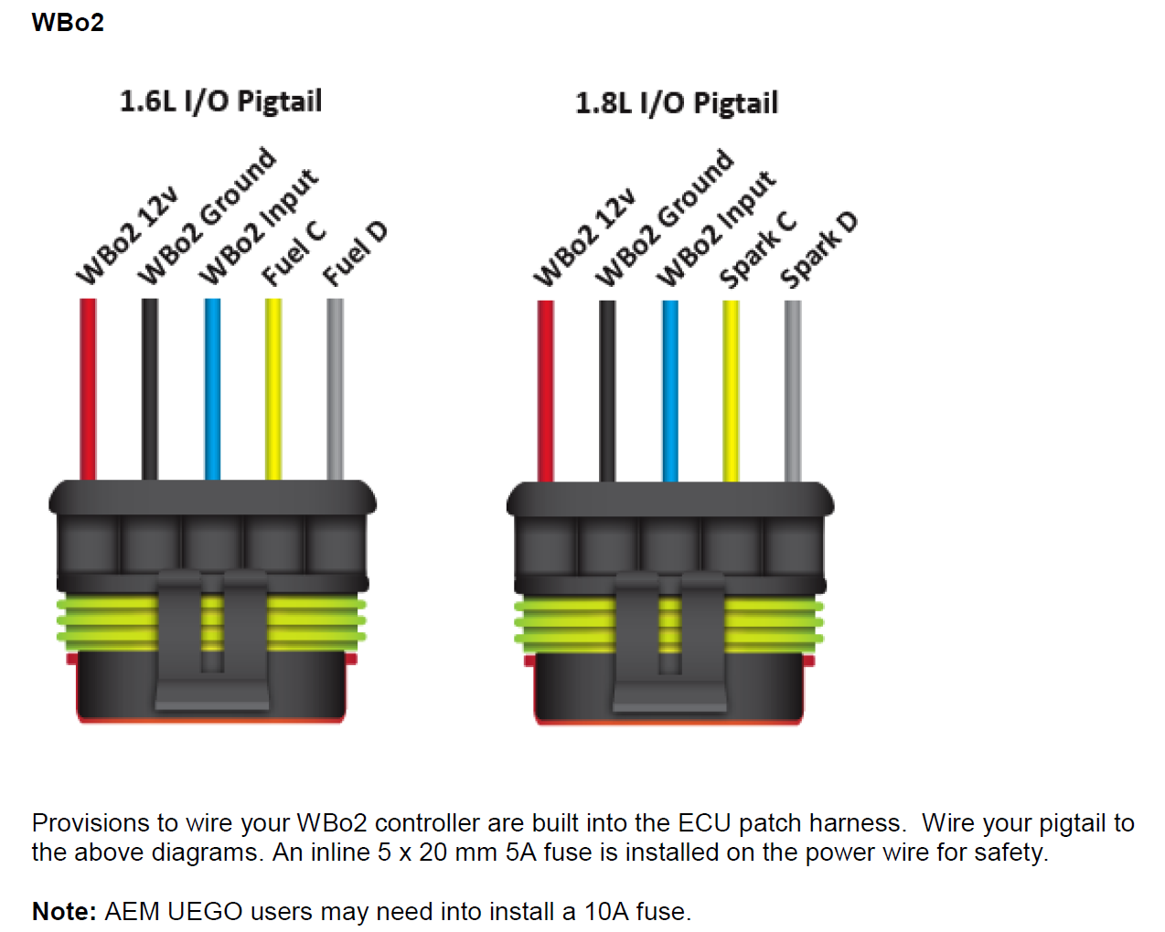
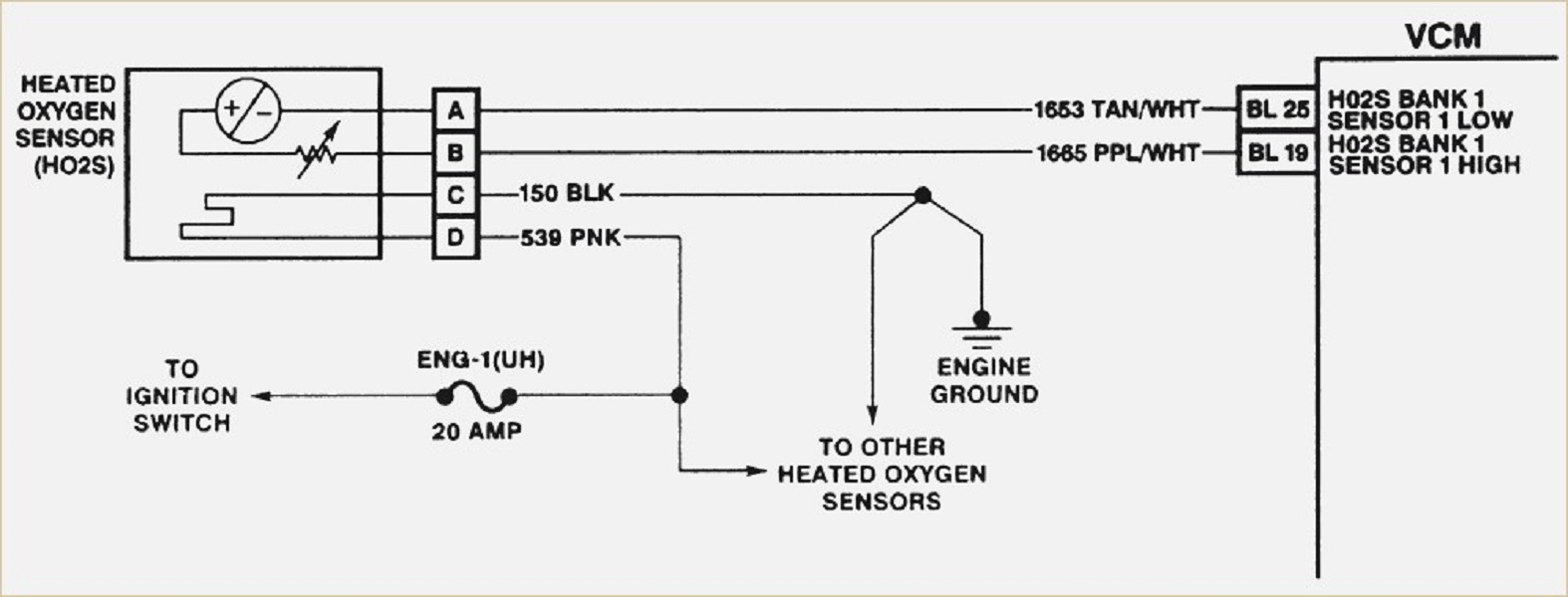
Heated 02 sensor wiring wiring diagram. Heated 02 sensor wiring wiring diagram. O2 sensor wiring diagram.this little pic is the wire side of the primary o2 sensor plug. Lambda bosch 5 wire wiring diagrams. Bosch 5 wire wideband o2 sensor wiring diagram wiring diagram line wiring diagram wiring diagram line we are make source the schematics, wiring diagrams and.

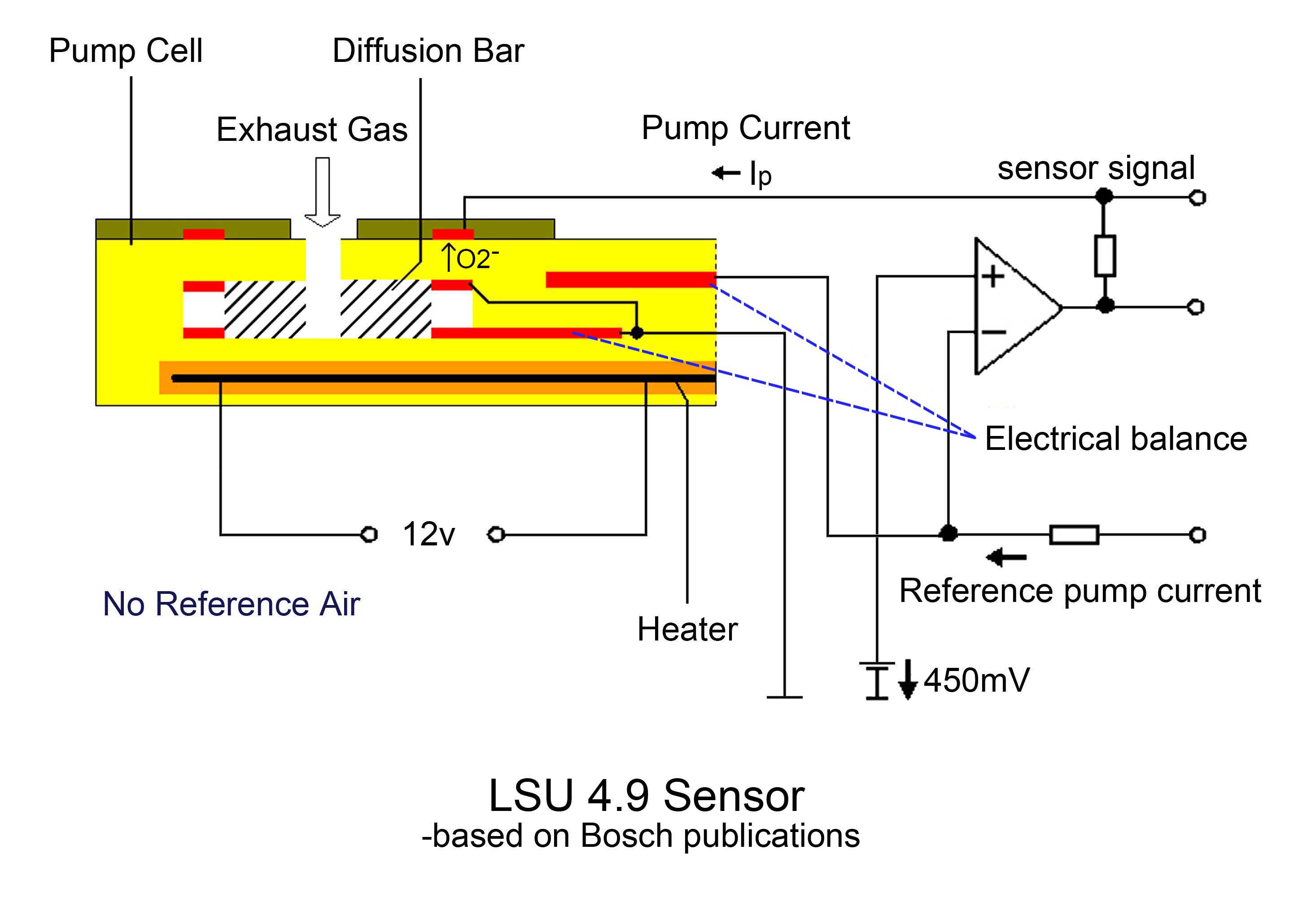
Lsu connectors and wiring how 5 wire sensors work tech edge wideband lambda club gti electronic fuel injection o2 sensor problems audiforums com bosch 4 9 wide band sonda 0258017025 ناعم air a f 2 broadband oxygen manual de instalación y ppt universal is superior to fiat strada saver magnum honda schematic diagram of ecu master range innovate lsu4 micro. 1x new bosch lsm11 4 wire wide band oxygen sensor o2 0258104002 For instance , if a module is usually powered up and it sends out a new signal of half the voltage and the technician will not know this, he would think he has a challenge, as he would expect the. Lambda bosch 5 wire wiring diagrams. This is the place to bosch wideband 5 wire oxygen sensor wiring diagram.

Otherwise, the structure will not function as it ought to be. Pin by doug brecheisen on wiring diagram car alternator car audio amplifier automotive electrical. The first component is symbol that indicate electric element in the circuit. It shows the components of the circuit as simplified shapes, and the gift and signal friends amid the devices. A wiring diagram is a streamlined standard pictorial depiction of an electrical circuit.
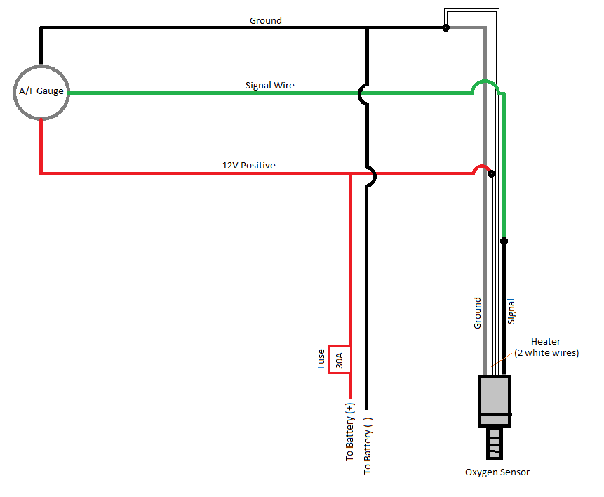 Source: schematron.org
It shows the components of the circuit as simplified shapes, and the gift and signal friends amid the devices. For instance , if a module is usually powered up and it sends out a new signal of half the voltage and the technician will not know this, he would think he has a challenge, as he would expect the 12v signal. The other thing which you will come across a circuit diagram could be traces. Check in this link wideband schematic: The most common configuration for modern cars is 4 wires.
 Source: chevydiagram.blogspot.com
The most common configuration for modern cars is 4 wires. Disconnect the o2 sensor from its electrical connector. Installation instruction for universal bosch oxygen sensor. • easily master 3 & 4 pin map sensor wiring diagram in 2 min. Oxygen sensor wiring diagram ford to properly read a electrical wiring diagram, one offers to learn how the particular components in the system operate.
![[DIAGRAM] 3 Wire O2 Sensor Wiring Diagram FULL Version HD [DIAGRAM] 3 Wire O2 Sensor Wiring Diagram FULL Version HD](https://ww2.justanswer.com/uploads/baddad1/2011-02-24_141910_capture.png) Source: webflowdiagrams.bumbleweb.fr
Source: webflowdiagrams.bumbleweb.fr
This is to allow for voltage losses in the controller circuitry and for more rapid heat up from cold, but it also means that for a long sensor life, the controller should be careful not to stress the sensor during warmup when large enough. For instance , if a module is usually powered up and it sends out a new signal of half the voltage and the technician will not know this, he would think he has a challenge, as he would expect the. Variety of 4 wire oxygen sensor wiring diagram. With the help of a buddy who works for honda i was able to find it and hopefully it will help someone with the same problem i had. Installation instruction for universal bosch oxygen sensor.
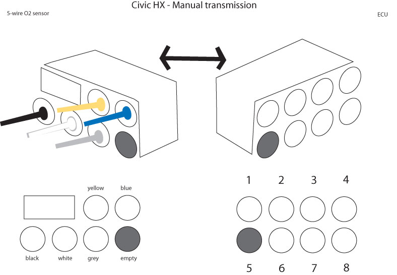 Source: honda-tech.com
Locate sensor wire:if none of these options are available, you�ll need to locate the oxygen senor and then locate the signal wire by testing. Pin by doug brecheisen on wiring diagram car alternator car audio amplifier automotive electrical. Bosch 5 wire wideband o2 sensor wiring diagram wiring diagram line wiring diagram wiring diagram line we are make source the schematics, wiring diagrams and. Variety of 4 wire oxygen sensor wiring diagram. Bank 1 is located on the passenger side of the engine compartment.
 Source: pinterest.com
The diagram shows black is ground, the red/yellow as the power/fuse wire, the white as ecm signal to computer wire and orange/black just has the abbreviation o2hfr. With this kind of an illustrative guide, you will be able to troubleshoot, prevent, and. Vr sensors are cheap and very rugged, hall effect sensors are much smaller, more expensive,. You should have received an instruction sheet in the box with the sensor. To properly read a electrical wiring diagram, one offers to learn how the particular components in the system operate.
 Source: fabiofalando.blogspot.com
With the help of a buddy who works for honda i was able to find it and hopefully it will help someone with the same problem i had. 4 wire o2 sensor wiring diagram ainulot. All wires are intact but i just can t figure out which goes where. 2)the new o2 has 2 browns, a purple and tan wire. For instance , if a module is usually powered up and it sends out a new signal of half the voltage and the technician will not know this, he would think he has a challenge, as he would expect the 12v signal.
 Source: asianhotgayx.blogspot.com
With this kind of an illustrative guide, you will be able to troubleshoot, prevent, and. Heated 02 sensor wiring wiring diagram. 5 wire oxygen sensor wiring diagram wiring diagram is a simplified up to standard pictorial representation of an electrical circuit. In this powerful guide, you will learn the wiring diagram of oxygen sensors such as 1, 2, 3, and 4 wire o2 sensor wiring diagrams. This is the place to bosch wideband 5 wire oxygen sensor wiring diagram.
 Source: aoshywii.blogspot.com
This should help out several members. For instance , if a module is usually powered up and it sends out a new signal of half the voltage and the technician will not know this, he would think he has a challenge, as he would expect the. I think it�s safe to say that the wrong o2 sensor is plugged into the existing pigtail based on the p0140 code. In this article, we make a short list of the best readers for bosch wideband o2 sensor wiring diagram including detail information and customer reviews. Variety of 4 wire oxygen sensor wiring diagram.
 Source: dreamer-angel-tattoo.blogspot.com
Related • cracking 3, 4, & 5 wire mass air flow sensor wiring diagram secrets. The first component is symbol that indicate electric element in the circuit. 1x new bosch lsm11 4 wire wide band oxygen sensor o2 0258104002 O2 sensor wiring diagram honda. The first element is symbol that indicate electric component in the circuit.
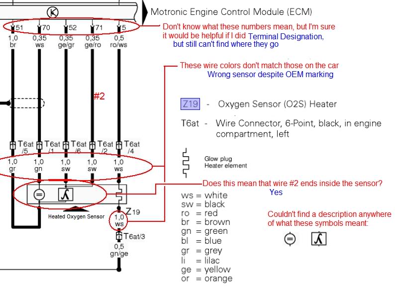 Source: audiforums.com
Check in this link wideband schematic: O2 sensor wiring diagram.this little pic is the wire side of the primary o2 sensor plug. Bosch oxygen sensor wiring diagram 3 wires. For instance , if a module is usually powered up and it sends out a new signal of half the voltage and the technician will not know this, he would think he has a challenge, as he would expect the. If the downstream rear oxygen sensor wiring harness contacts the propeller drive shaft it can damage the oxygen sensor and the wiring harness for the sensor andor cause check engine light illumination.
![[DIAGRAM] Wiring Diagram Universal Oxygen Sensor FULL [DIAGRAM] Wiring Diagram Universal Oxygen Sensor FULL](https://desbennettconsultants.netlify.app/img/placeholder.svg)
5 wire oxygen sensor wiring diagram. For instance , if a module is usually powered up and it sends out a new signal of half the voltage and the technician will not know this, he would think he has a challenge, as he would expect the. There are two things which are going to be present in almost any o2 sensor wiring diagram chevy. In this powerful guide, you will learn the wiring diagram of oxygen sensors such as 1, 2, 3, and 4 wire o2 sensor wiring diagrams. There are just two things that will be present in almost any 4 wire oxygen sensor wiring diagram.
 Source: justanswer.com
It shows the components of the circuit as simplified shapes, and the gift and signal friends amid the devices. Installation bosch o2 sensor with smartlink. To test, set the multimeter to resistance mode and use it to probe and figure out which wires register a. There are two things which are going to be present in almost any o2 sensor wiring diagram chevy. Installation instruction for universal bosch oxygen sensor.
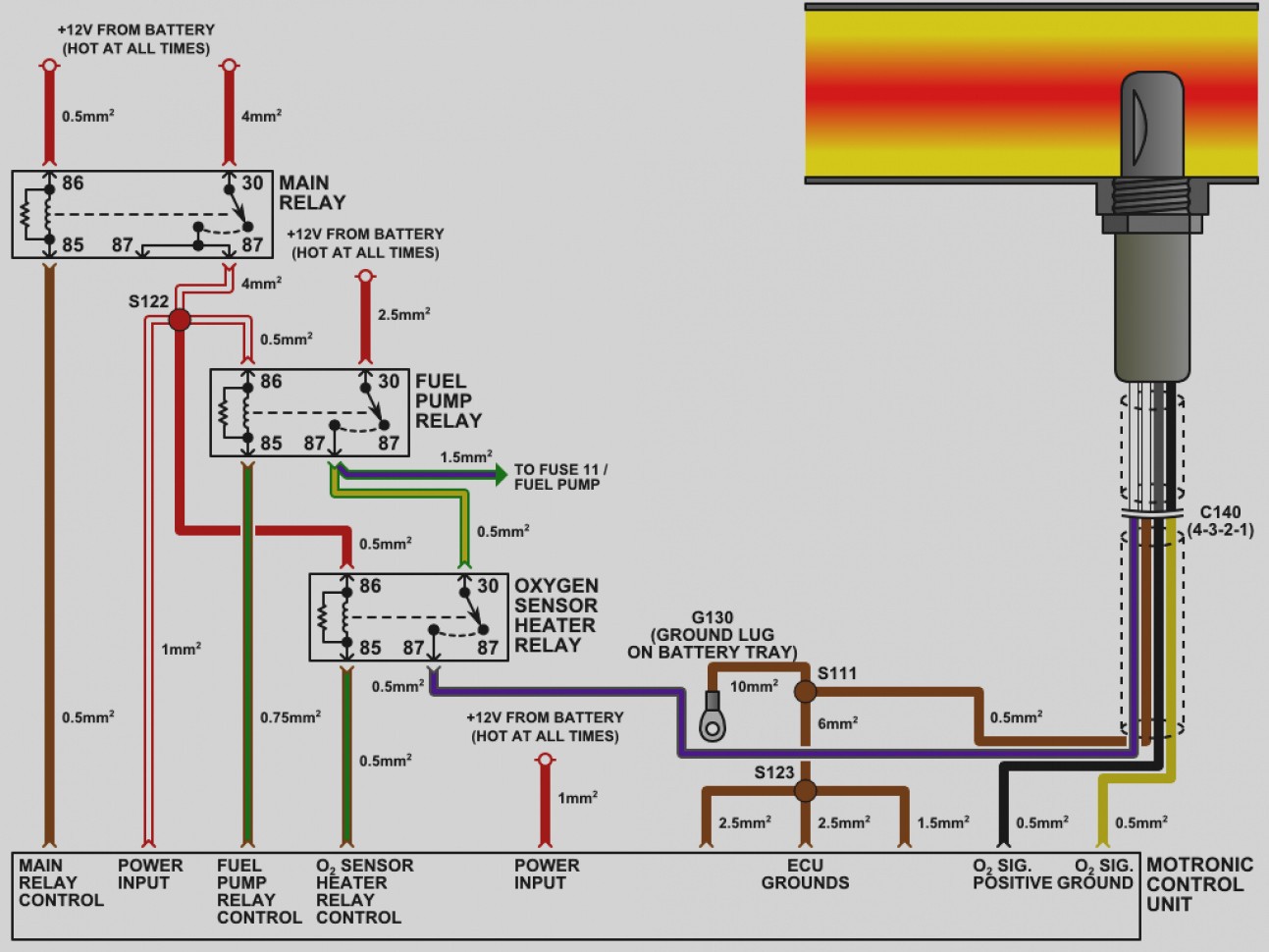 Source: wiringdiagram.2bitboer.com
Lsu connectors and wiring how 5 wire sensors work tech edge wideband lambda club gti electronic fuel injection o2 sensor problems audiforums com bosch 4 9 wide band sonda 0258017025 ناعم air a f 2 broadband oxygen manual de instalación y ppt universal is superior to fiat strada saver magnum honda schematic diagram of ecu master range innovate lsu4 micro. Pin by doug brecheisen on wiring diagram car alternator car audio amplifier automotive electrical. With the help of a buddy who works for honda i was able to find it and hopefully it will help someone with the same problem i had. This should be done first. 5 wire oxygen sensor wiring diagram wiring diagram is a simplified up to standard pictorial representation of an electrical circuit.
 Source: 2020cadillac.com
The first element is symbol that indicate electric component in the circuit. Heated 02 sensor wiring wiring diagram. 3)the instructions it came with say connect blue to signal wire, two blacks to to either heater wires. You should have received an instruction sheet in the box with the sensor. For instance , if a module is usually powered up and it sends out a new signal of half the voltage and the technician will not know this, he would think he has a challenge, as he would expect the 12v signal.
This site is an open community for users to do sharing their favorite wallpapers on the internet, all images or pictures in this website are for personal wallpaper use only, it is stricly prohibited to use this wallpaper for commercial purposes, if you are the author and find this image is shared without your permission, please kindly raise a DMCA report to Us.
If you find this site adventageous, please support us by sharing this posts to your favorite social media accounts like Facebook, Instagram and so on or you can also bookmark this blog page with the title 5 wire o2 sensor wiring diagram by using Ctrl + D for devices a laptop with a Windows operating system or Command + D for laptops with an Apple operating system. If you use a smartphone, you can also use the drawer menu of the browser you are using. Whether it’s a Windows, Mac, iOS or Android operating system, you will still be able to bookmark this website.

