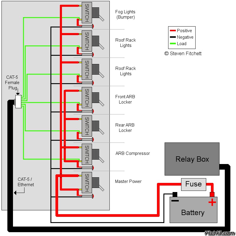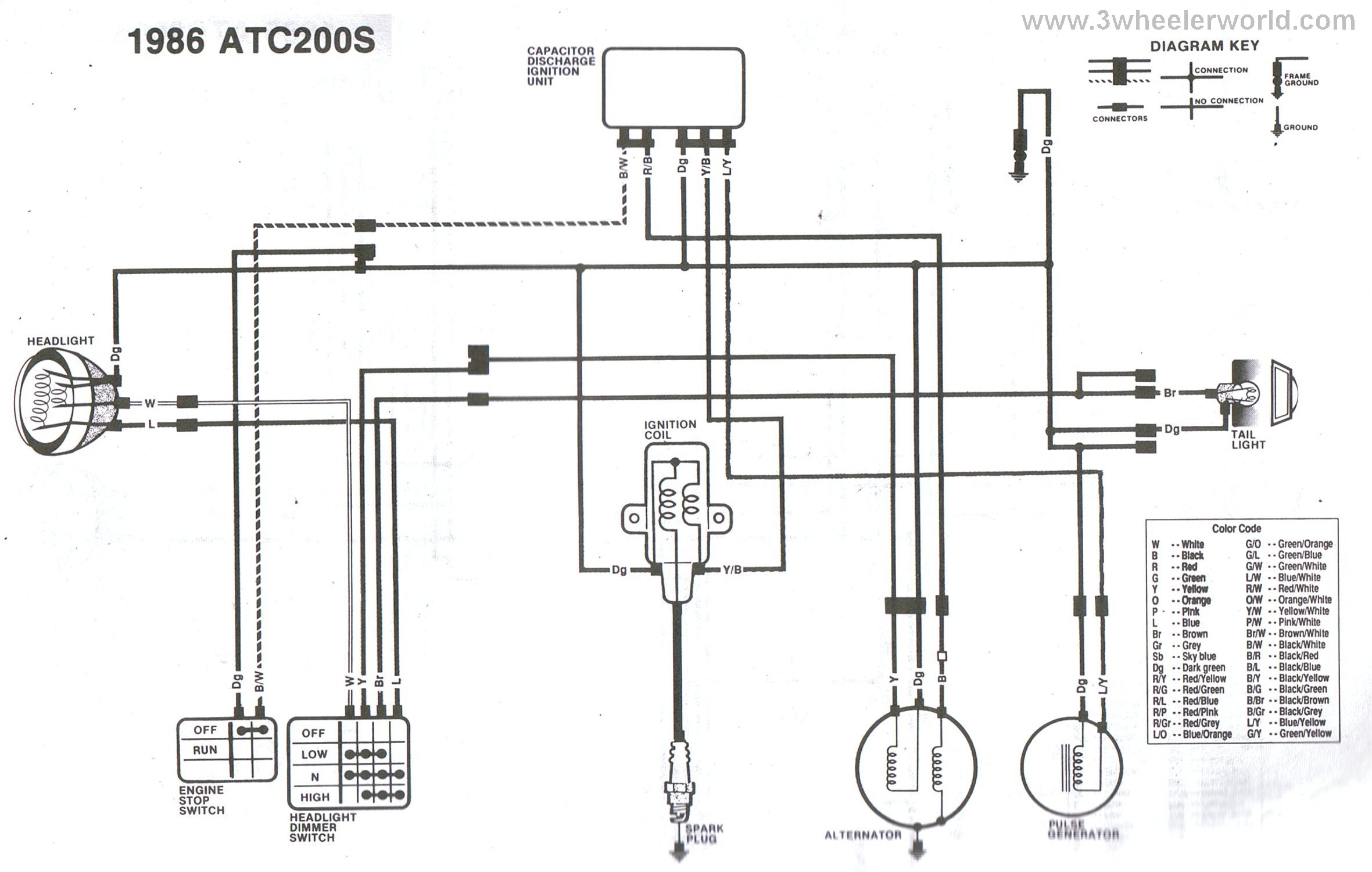
Your 415v to 110v transformer wiring diagram images are available in this site. 415v to 110v transformer wiring diagram are a topic that is being searched for and liked by netizens now. You can Find and Download the 415v to 110v transformer wiring diagram files here. Get all free photos and vectors.
If you’re searching for 415v to 110v transformer wiring diagram images information linked to the 415v to 110v transformer wiring diagram keyword, you have come to the right blog. Our website always provides you with hints for seeking the maximum quality video and picture content, please kindly hunt and locate more enlightening video content and graphics that match your interests.
415v To 110v Transformer Wiring Diagram. Before selecting a transformer for a system, it is important to understand its earthing system whether it is neutral earthing or centre tap earthing. By having a wrong transformer for the application may cause damage to the connecting devices. Wv 380~480v to 24v or 48v transformer (50va~3kva) from £17.00 add to basket quick view; Electric, how to wire a three prong 110v ac plug hunker, wiring controlling 110v swamp cooler using nest, iet forums 415v 3phase to 110v 3phase transformer wiring, 220v hot tub wiring diagram free wiring diagram, manual of 110v 220v motor lilly electronics, 110v schematic wiring diagram sparkeroding co uk, 110v outlet wiring diagram
 PHASE FAILURE RELAYS WITH UNDER VOLTAGE CONTROL & TRUE From foxtamcontrols.co.uk
Before selecting a transformer for a system, it is important to understand its earthing system whether it is neutral earthing or centre tap earthing. Login / register to view discount. October 2007 rev4 page 1 of 9 For the following diagrams, 110v cte will be used. The dv range is an adaption of our popular single voltage (sv) range. Each component ought to be set and connected with other parts in specific way.
The 5kva 400v will have line currents of 3.9amps / 10.6amps / 14.5amps
415v delta primary (input) x 110 secondary (output). He needs batteres to supply the 1500w loads for 12hours at night. Wiring diagrams for mta, mtc and ap transformers. Sv single voltage 240v to 24v transformer (25va~1kva) from £12.20 add to basket quick view; Electric, how to wire a three prong 110v ac plug hunker, wiring controlling 110v swamp cooler using nest, iet forums 415v 3phase to 110v 3phase transformer wiring, 220v hot tub wiring diagram free wiring diagram, manual of 110v 220v motor lilly electronics, 110v schematic wiring diagram sparkeroding co uk, 110v outlet wiring diagram Wiring four 110v 50a step down xformers via 220v.
 Source: pinterest.com
The 5kva 400v will have line currents of 3.9amps / 10.6amps / 14.5amps Transformer kit (transformer, fuses, wiring) c ce c341 25 50 75 100 150 200 250 300 350 500 750 1000 1500 2000 3000 5000 type ap only: Voltage at no load is 240v and 61hz. Dol starter direct online wiring diagram working principle electrical4u what will happen to a contactor with coil 220v energized 110v its it function normally or have any bad effect quora direct on line dol motor The actual load is a tad over 2kva but you need that bit extra.
 Source: convret.blogspot.com
The diagram below refers to the colour scheme that i�ve more commonly found on transformers. Before selecting a transformer for a system, it is important to understand its earthing system whether it is neutral earthing or centre tap earthing. A control transformer is an isolation transformer designed to provide a high degree of secondary voltage stability (regulation) during a brief period of overload condition (also referred to as “inrush current”). Wiring diagram for transformer wiring diagram is a simplified within acceptable limits pictorial representation of an electrical circuit. Ab plc wiring diagram 480v to 240v transformer wiring diagram 240v to 480v step up transformer wiring diagram 480v 3 phase to 240v single phase transformer wiring diagram 480v to 240v 3 phase transformer wiring diagram every electric arrangement is composed of various unique components.
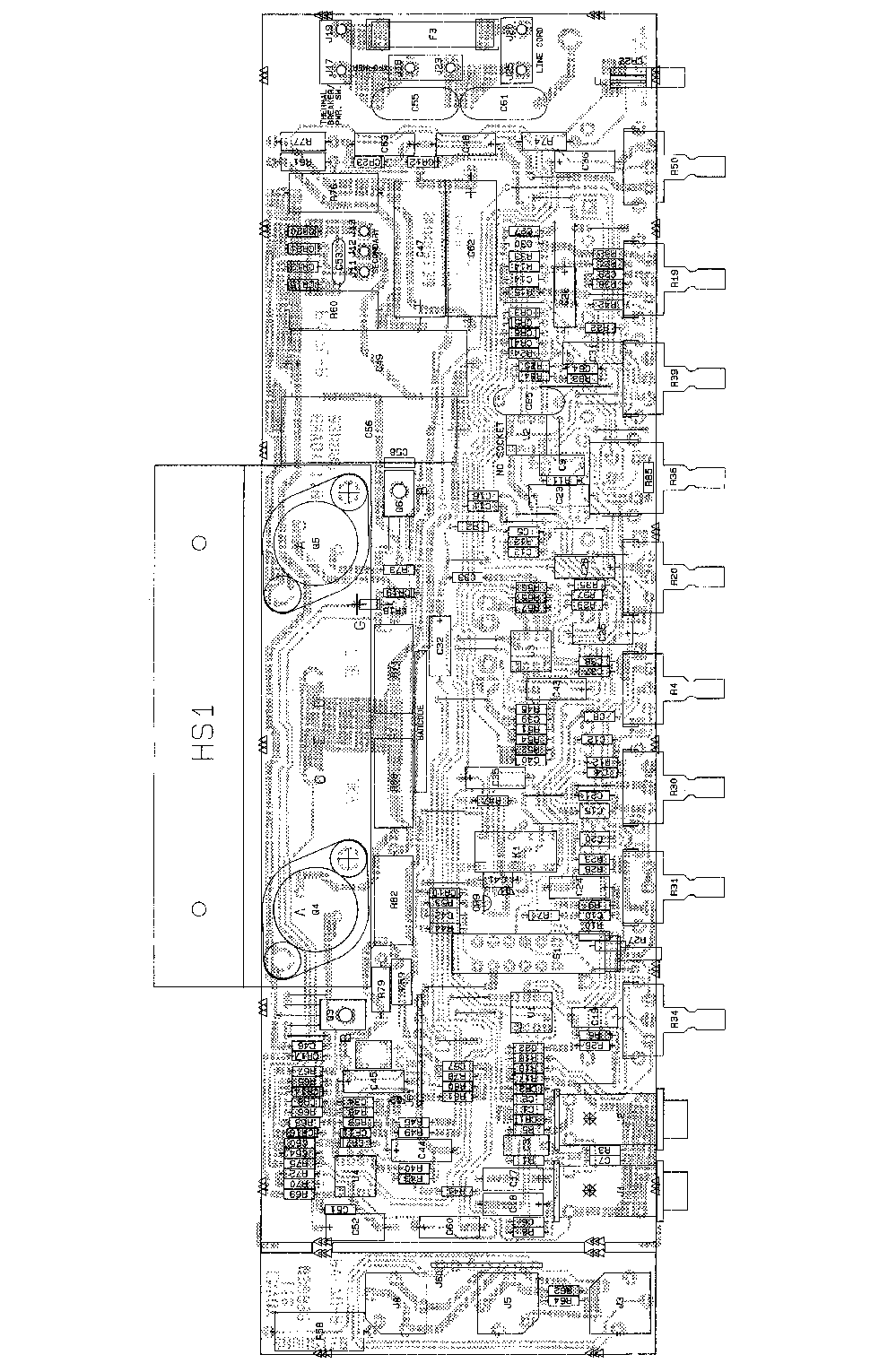 Source: wiringmanualpdf.blogspot.com
October 2007 rev4 page 1 of 9 For the following diagrams, 110v cte will be used. Transformer kit (transformer, fuses, wiring) c ce c341 25 50 75 100 150 200 250 300 350 500 750 1000 1500 2000 3000 5000 type ap only: Control transformers are also known as machine tool transformers, industrial control transformers or control power transformers. The main transformer rating is equivalent to 90% of the load rating and the teaser transformer about 70% giving a total of 160% of the load rating.
Source: wiringideas.blogspot.com
Electric, how to wire a three prong 110v ac plug hunker, wiring controlling 110v swamp cooler using nest, iet forums 415v 3phase to 110v 3phase transformer wiring, 220v hot tub wiring diagram free wiring diagram, manual of 110v 220v motor lilly electronics, 110v schematic wiring diagram sparkeroding co uk, 110v outlet wiring diagram 3000 5000 7500 10000 15000. The main transformer rating is equivalent to 90% of the load rating and the teaser transformer about 70% giving a total of 160% of the load rating. This makes 9 wires for 415v input and 110v and 240v output. 4 x 16a 2p+e 110v en 60309 (bs 4343) sockets.
 Source: windingphotos.blogspot.com
Volt 240 swallow 6 208v larson electronics 500 va 440v 460v 480v amp 690v input voltage output product 100v acme 380v 415v 220v 50 491x29 tb50n016 grainger mfg classic plate filament universal 260. So i�m fairly sure this is a single phase transformer. Secondary are two 115v windings so parallel for 115v and series for 230v. The diagrams below are a repeat of the antrim ® page linked above, for the convenience of printing and reminding you how to wire these transformers. Transformation along the power path.
 Source: wiring-pdf.blogspot.com
4 x 16a 2p+e 110v en 60309 (bs 4343) sockets. By having a wrong transformer for the application may cause damage to the connecting devices. Ab plc wiring diagram 480v to 240v transformer wiring diagram 240v to 480v step up transformer wiring diagram 480v 3 phase to 240v single phase transformer wiring diagram 480v to 240v 3 phase transformer wiring diagram every electric arrangement is composed of various unique components. A 4kva 415/110v 3ph transformer will give a bit of headroom for starting. Dv dual input voltage 240v or 415v to 110v transformer (50va~1kva)
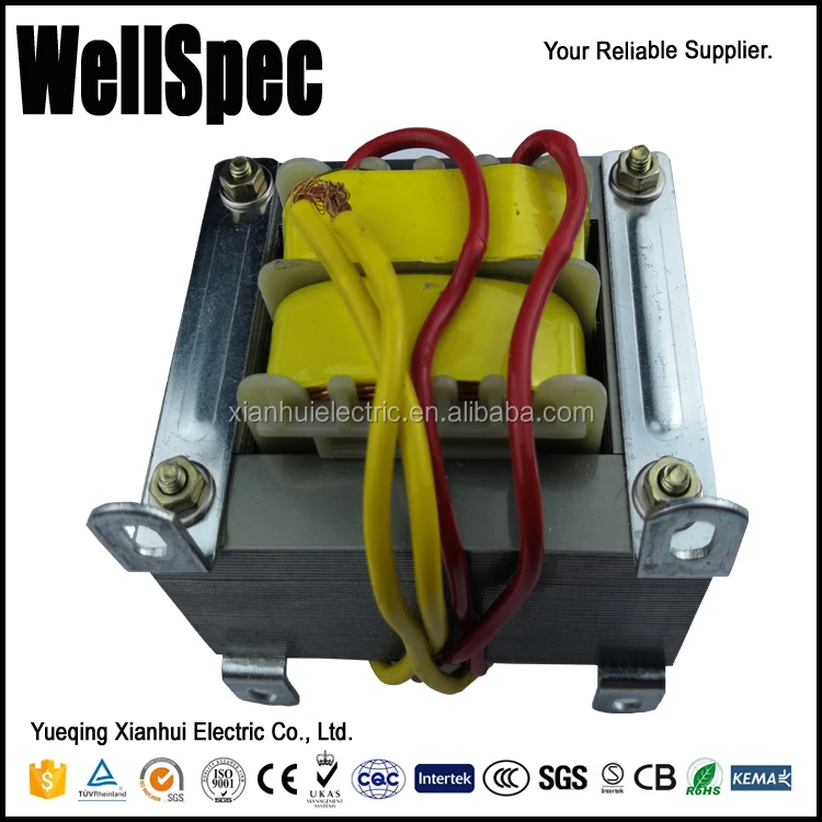 Source: alibaba.com
October 2007 rev4 page 1 of 9 4 x 16a 2p+e 110v en 60309 (bs 4343) sockets. Ratings range from 50va to 1kva. Control transformers are also known as machine tool transformers, industrial control transformers or control power transformers. 3000 5000 7500 10000 15000.
 Source: convret.blogspot.com
Volt 240 swallow 6 208v larson electronics 500 va 440v 460v 480v amp 690v input voltage output product 100v acme 380v 415v 220v 50 491x29 tb50n016 grainger mfg classic plate filament universal 260. Transformation along the power path. The main transformer rating is equivalent to 90% of the load rating and the teaser transformer about 70% giving a total of 160% of the load rating. Electric, how to wire a three prong 110v ac plug hunker, wiring controlling 110v swamp cooler using nest, iet forums 415v 3phase to 110v 3phase transformer wiring, 220v hot tub wiring diagram free wiring diagram, manual of 110v 220v motor lilly electronics, 110v schematic wiring diagram sparkeroding co uk, 110v outlet wiring diagram He needs batteres to supply the 1500w loads for 12hours at night.
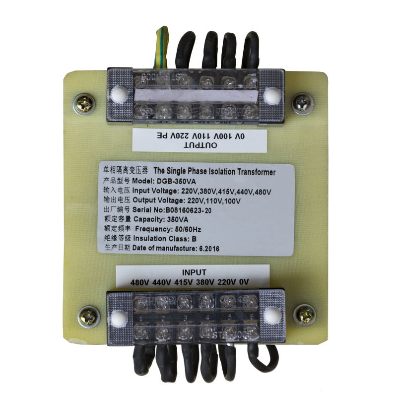 Source: german.acpowerstabilizer.com
They are tapped at 0/240/415v with output options of 24v, 100v, or 240v. Login / register to view discount. You probably connect one phase of the 415v to the transformer to step down to the 2. Secondary are two 115v windings so parallel for 115v and series for 230v. Transformation along the power path.
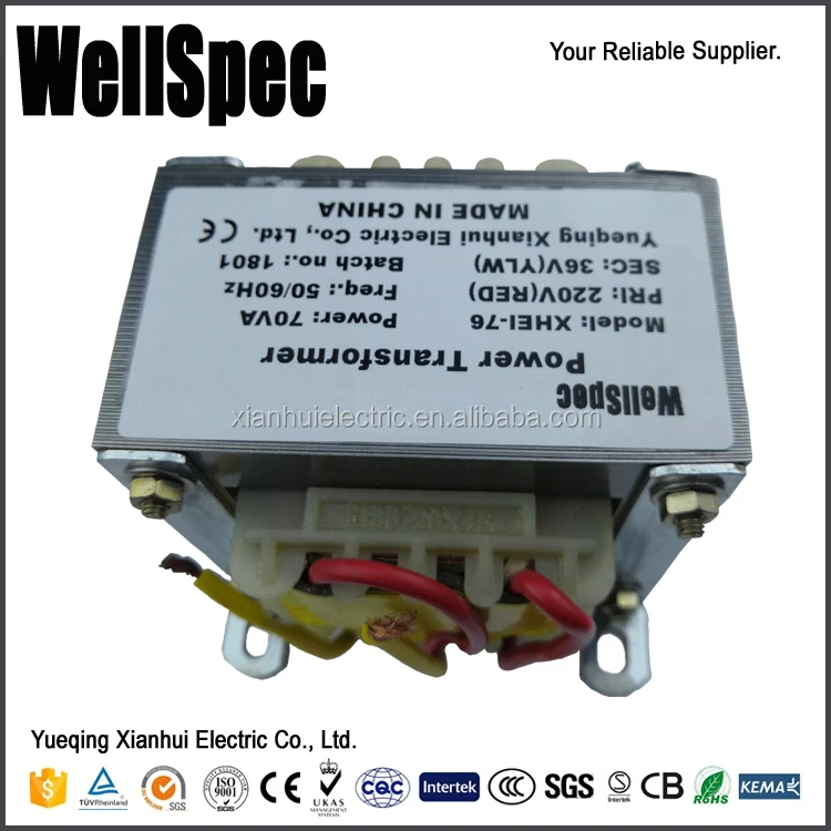 Source: alibaba.com
Control transformers are also known as machine tool transformers, industrial control transformers or control power transformers. Transformer kit (transformer, fuses, wiring) c ce c341 25 50 75 100 150 200 250 300 350 500 750 1000 1500 2000 3000 5000 type ap only: 120/240 2, 21/2% anfc, 4, 2 /2% bnfc. Sv single voltage 240v to 24v transformer (25va~1kva) from £12.20 add to basket quick view; The 5kva 400v will have line currents of 3.9amps / 10.6amps / 14.5amps
 Source: foxtamcontrols.co.uk
By having a wrong transformer for the application may cause damage to the connecting devices. Voltage at no load is 240v and 61hz. Also a three phase transformer doesn�t convert three phases into one phase, but the image shows only one connection (aka phase) for each voltage. Before selecting a transformer for a system, it is important to understand its earthing system whether it is neutral earthing or centre tap earthing. 400v 120v transformer wiring diagram wiring diagram line wiring diagram.
 Source: acpowerstabilizer.com
The actual load is a tad over 2kva but you need that bit extra. Dol starter direct online wiring diagram working principle electrical4u what will happen to a contactor with coil 220v energized 110v its it function normally or have any bad effect quora direct on line dol motor Control transformers are also known as machine tool transformers, industrial control transformers or control power transformers. Dv dual input voltage 240v or 415v to 110v transformer (50va~1kva) In this single phase home supply wiring diagram the main supply single phase live red wire and neutral black wire comes from the secondary of the transformer 3 phase 4 wire star system to the single phase energy meter note that single phase supply is 230v ac and 120v ac in us.
Source: gumtree.com
The diagrams below are a repeat of the antrim ® page linked above, for the convenience of printing and reminding you how to wire these transformers. Before selecting a transformer for a system, it is important to understand its earthing system whether it is neutral earthing or centre tap earthing. By having a wrong transformer for the application may cause damage to the connecting devices. Control transformers are also known as machine tool transformers, industrial control transformers or control power transformers. Each component ought to be set and connected with other parts in specific way.
 Source: digitalmeter-suppliers.com
Ratings range from 50va to 1kva. Wiring four 110v 50a step down xformers via 220v. 3000 5000 7500 10000 15000. This makes 9 wires for 415v input and 110v and 240v output. With under 1hp motor and a 415v transformer in it.
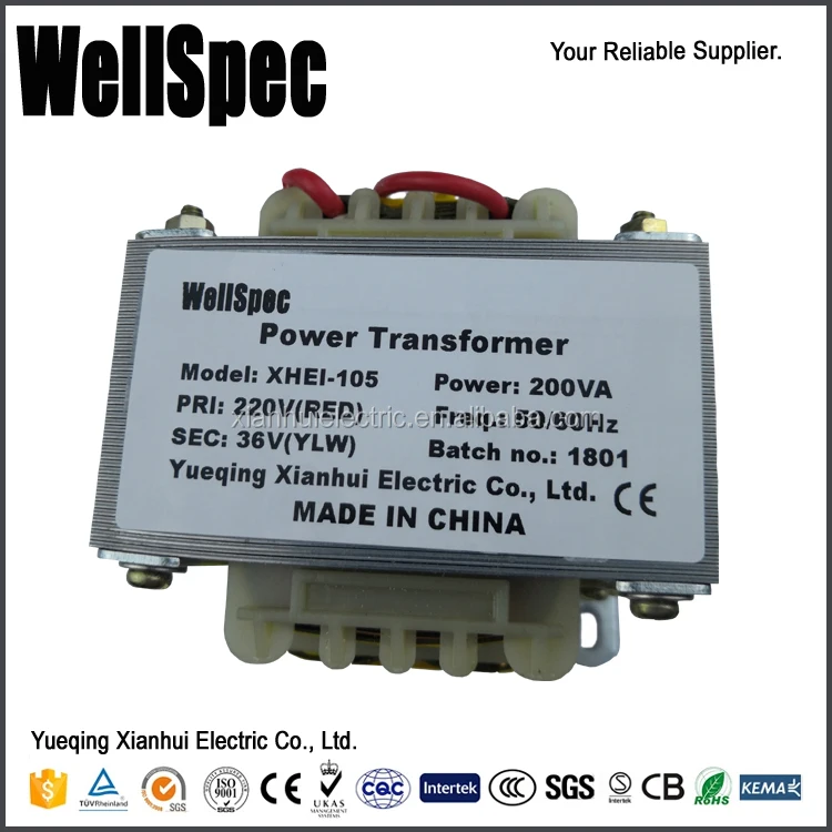 Source: alibaba.com
Shop our range of din rail & panel mount transformers supplies & accessories. A 4kva 415/110v 3ph transformer will give a bit of headroom for starting. 400v 120v transformer wiring diagram wiring diagram line wiring diagram. Sv single voltage 240v to 24v transformer (25va~1kva) from £12.20 add to basket quick view; Also a three phase transformer doesn�t convert three phases into one phase, but the image shows only one connection (aka phase) for each voltage.
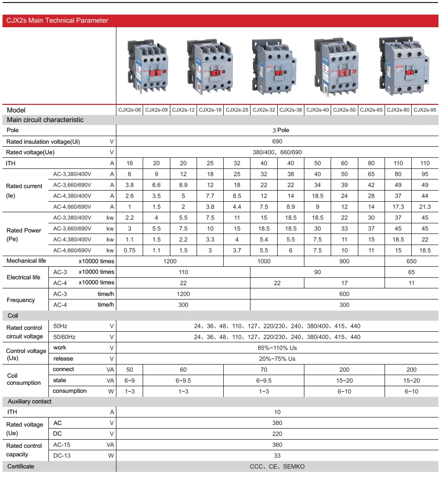 Source: alibaba.com
Wiring four 110v 50a step down xformers via 220v. Wiring diagram for transformer wiring diagram is a simplified within acceptable limits pictorial representation of an electrical circuit. Secondary are two 115v windings so parallel for 115v and series for 230v. For the following diagrams, 110v cte will be used. A 4kva 415/110v 3ph transformer will give a bit of headroom for starting.
 Source: wiringmanualpdf.blogspot.com
He needs batteres to supply the 1500w loads for 12hours at night. The actual load is a tad over 2kva but you need that bit extra. Login / register to view discount. Sv single voltage 240v to 24v transformer (25va~1kva) from £12.20 add to basket quick view; 3000 5000 7500 10000 15000.
 Source: acpowerstabilizer.com
110v ac 50/60hz output voltage. Transformation along the power path. 415v delta primary (input) x 110 secondary (output). Dv dual input voltage 240v or 415v to 110v transformer (50va~1kva) X4x1 h4 h3 h2 h1 x2x3.
This site is an open community for users to submit their favorite wallpapers on the internet, all images or pictures in this website are for personal wallpaper use only, it is stricly prohibited to use this wallpaper for commercial purposes, if you are the author and find this image is shared without your permission, please kindly raise a DMCA report to Us.
If you find this site good, please support us by sharing this posts to your preference social media accounts like Facebook, Instagram and so on or you can also save this blog page with the title 415v to 110v transformer wiring diagram by using Ctrl + D for devices a laptop with a Windows operating system or Command + D for laptops with an Apple operating system. If you use a smartphone, you can also use the drawer menu of the browser you are using. Whether it’s a Windows, Mac, iOS or Android operating system, you will still be able to bookmark this website.


