Your 4 wire photo sensor wiring diagram images are available in this site. 4 wire photo sensor wiring diagram are a topic that is being searched for and liked by netizens now. You can Find and Download the 4 wire photo sensor wiring diagram files here. Get all free vectors.
If you’re looking for 4 wire photo sensor wiring diagram pictures information linked to the 4 wire photo sensor wiring diagram interest, you have visit the ideal blog. Our site frequently provides you with suggestions for seeing the maximum quality video and image content, please kindly surf and find more informative video content and images that fit your interests.
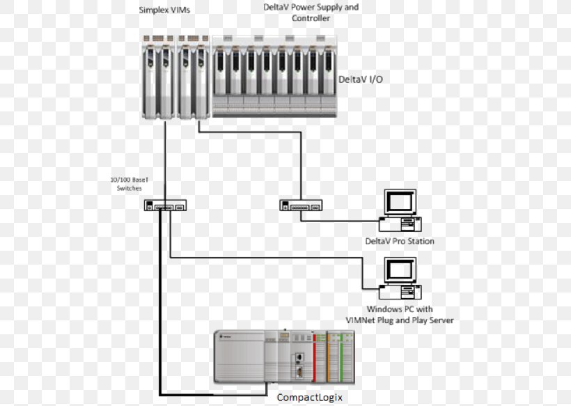
4 Wire Photo Sensor Wiring Diagram. L1 and l3 carry the measuring current while l2 acts only as a potential lead. Wiring diagram schematic 4 wire trailer light of four in. Photo eye sensor wiring diagram.connect all 3 white wires from house from sensor and from light. Npn_pnp 4 wire sensors.vsd faq please refer to our tech support website for more info on sensors.
 8 Images Installing 5 Wire Ceiling Fan Capacitor And From alquilercastilloshinchables.info
When using thermocouple and rtd sensors, the 4 wire proximity switch wiring diagram. 4 wire o2 sensor wiring diagram nissan. 4 wire rtd wiring diagram in this circuit there are three leads coming from the rtd instead of two. The first component is symbol that indicate electric component in the circuit. 36 unexceeded mental picture of lighting contactor wiring diagram in 2021 diagram electricity wire.
Transmitters are available with a wide variety of signal outputs.
4 wire photo sensor wiring diagram december 11, 2021. Here are some fully explained 4 way switch diagrams. Usb to serial cable wiring diagram virtual fretboard and gif 1168 1313 usb cable electronics basics computer love. Wiring diagram for npn and pnp 4 wire sensors d2 16nd3 2 an easy way to remember pnp and npn sensor wiring automation insights dr18 series cylinderical photoelectric sensors photo switches fiber optical sensor Home decorating style 2022 for 4 wire 02 sensor diagram, you can see 4 wire 02 sensor diagram and more pictures for home interior designing 2022 318288 at resume example ideas. For instance , if a module is usually powered up and it sends out a new signal of half the voltage and the technician will not know this, he would think he has a challenge, as he would.
 Source: wiringforums.com
By looking at a wiring diagram here provided by mitchell 1 prodemand we can by simply matching colors figure out which wires belong to the oxygen sensor heater circuit. 36 unexceeded mental picture of lighting contactor wiring diagram in 2021 diagram electricity wire. Repeat this for the neutral white wires and red load wires. The other thing you will come across a. With this kind of an illustrative guidebook, you are going to be capable of troubleshoot, avoid, and full your assignments easily.
 Source: youtube.com
Answer :you must use at least three; Repeat this for the neutral white wires and red load wires. By looking at a wiring diagram here provided by mitchell 1 prodemand we can by simply matching colors figure out which wires belong to the oxygen sensor heater circuit. Black wire is 120 volts, so turn off switch or circuit breaker. Do not cut wires while removing the existing sensor from the vehicle.
 Source: justanswer.com
Taotao 110cc atv wire diagram on back of key switch atvconnection com enthusiast community 4 wire ignition key switch atv pit 6v 50cc 70cc 90cc 110cc 125cc for taotao peace pins canada cspart linhai 250 260 300 400 ignition key switch lock set 4 wires for atv dirt pocket pit bike online in turkey b073pqgshk L1 and l3 carry the measuring current while l2 acts only as a potential lead. Connect all 3 white wires (from house, from sensor and from light) together. Twist the hot black wires together and screw a plastic wire nut onto the ends. That is, if the sensor is pnp for the black wire, it is also pnp for the white wire.
 Source: dentistmitcham.com
The maf signal wire goes to the car ecu. Wiring diagram for npn and pnp 4 wire sensors d2 16nd3 2 an easy way to remember sensor automation insights dr18 series cylinderical photoelectric photo switches fiber optical two inductive proximity the universal donor 3 how read datasheet realpars carlo gavazzi lj12a3 capacity solid state relay pcb. This guidance note aims to outline these options. Otherwise, the structure won’t function as it should be. By looking at a wiring diagram here provided by mitchell 1 prodemand we can by simply matching colors figure out which wires belong to the oxygen sensor heater circuit.
 Source: untpikapps.com
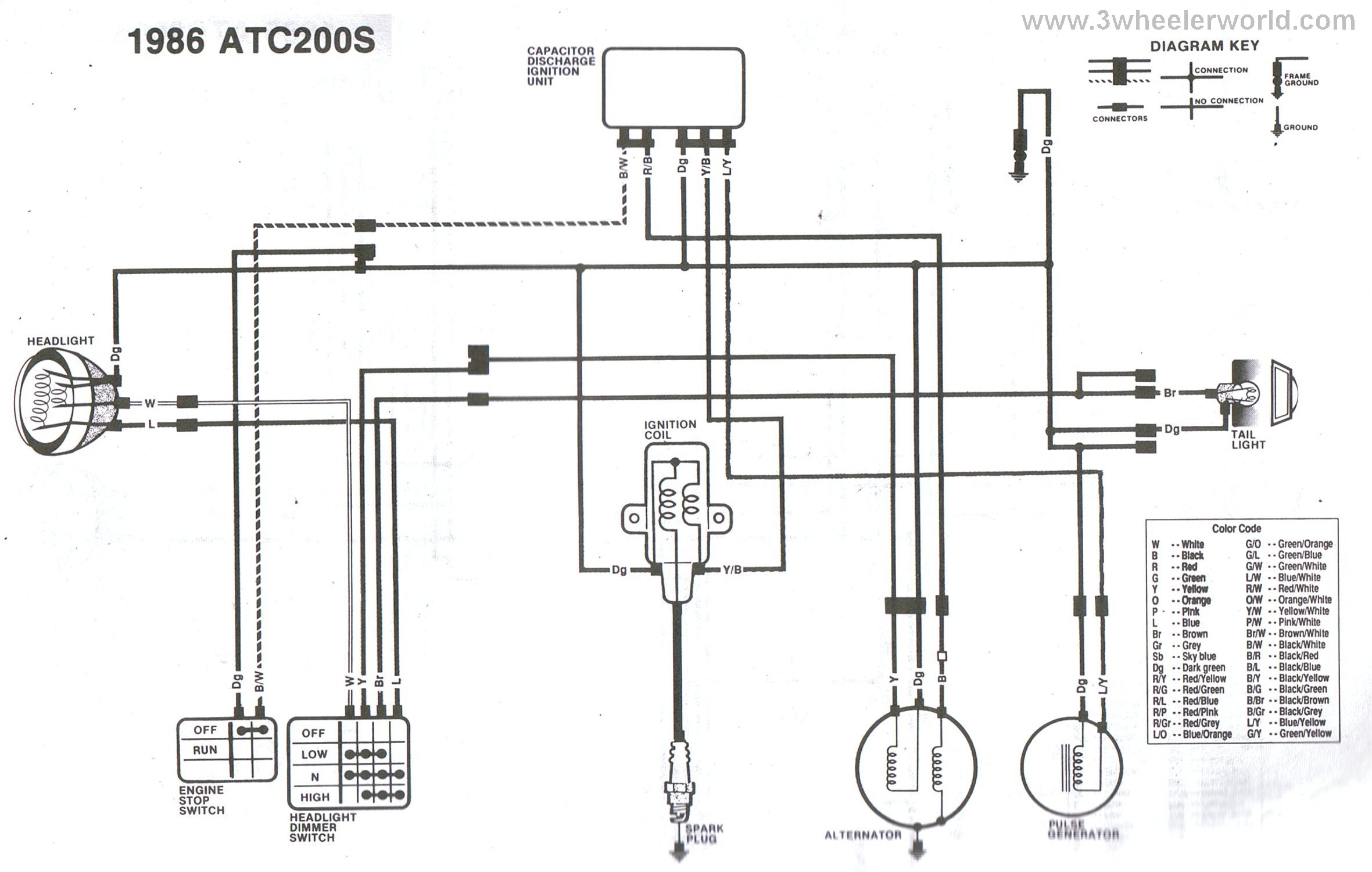
Wiring diagram for npn and pnp 4 wire sensors d2 16nd3 2 an easy way to remember sensor automation insights dr18 series cylinderical photoelectric photo switches fiber optical two inductive proximity the universal donor 3 how read datasheet realpars carlo gavazzi lj12a3 capacity solid state relay pcb. The first component is symbol that indicate electric component in the circuit. 4 wire oxygen sensor wiring diagram.you will need the wiring diagram for the car the oxygen sensor has 4 wires two white which are the heater one positive one negative it doesnt matter which is which the black is ground the gray is the signal wire some have a blue wire black is always ground the blue would be sensor hope this helps. The picture is just an example of any 4 wire o2 sensor. 4 wire photo sensor wiring diagram december 11, 2021.
 Source: diagramweb.net
The live and neutral wires are. There are two things that will be found in any wiring a motion sensor light diagram. The first component is symbol that indicate electric component in the circuit. 4 wire photo sensor wiring diagram december 11, 2021. Do not cut wires while removing the existing sensor from the vehicle.
 Source: ceilingfanswitch.com
There are two things that will be found in any wiring a motion sensor light diagram. 4 wire photo sensor wiring diagram december 11, 2021. The maf signal wire goes to the car ecu. Repeat this for the neutral white wires and red load wires. I did a print screen of the o2 wiring diagram from my bentley cd.
 Source: youtube.com
The first component is symbol that indicate electric component in the circuit. 4 wire photo sensor wiring diagram december 11, 2021. Repeat this for the neutral white wires and red load wires. The sinking / sourcing logic is the same as for the black wire. Each component ought to be placed and connected with different parts in particular manner.
 Source: electricalonline4u.com
For instance , if a module is usually powered up and it sends out a new signal of half the voltage and the technician will not know this, he would think he has a challenge, as he would. With this kind of an illustrative guidebook, you are going to be capable of troubleshoot, avoid, and full your assignments easily. This guidance note aims to outline these options. The wiring diagram for the wideband sensor typically has six wires:. A wiring diagram is a streamlined standard pictorial depiction of an electrical circuit.
 Source: audizine.com
36 unexceeded mental picture of lighting contactor wiring diagram in 2021 diagram electricity wire. Here is my wiring diagram ( third photo) and instructions: 4 wire rtd wiring diagram in this circuit there are three leads coming from the rtd instead of two. No current flows through it while the bridge is in balance.since l1 and l3 are in separate arms of the bridge,resistance is canceled. 16 point dc input module last revised :
 Source: pinterest.com
Answer :you must use at least three; 4 wire rtd wiring diagram in this circuit there are three leads coming from the rtd instead of two. 16 point dc input module last revised : Connect red sensor wire to light�s black wire. Home decorating style 2022 for 4 wire 02 sensor diagram, you can see 4 wire 02 sensor diagram and more pictures for home interior designing 2022 318288 at resume example ideas.
 Source: untpikapps.com
December 12, 2020 · wiring diagram. 15 feb, 2002 document name: This guidance note aims to outline these options. Taotao 110cc atv wire diagram on back of key switch atvconnection com enthusiast community 4 wire ignition key switch atv pit 6v 50cc 70cc 90cc 110cc 125cc for taotao peace pins canada cspart linhai 250 260 300 400 ignition key switch lock set 4 wires for atv dirt pocket pit bike online in turkey b073pqgshk The sensor black wire will connect to the hot wire in the wallbox.
 Source: diagramweb.net
The fa q section may have information that can help. The 4 pin m12 plug (standard) is broken down as follows: Bosch diagram and see can i still use that 4 wire denso sensor or i. Connect all 3 white wires (from house, from sensor and from light) together. There are two things that will be found in any wiring a motion sensor light diagram.
 Source: mgispeedware.com
I need to reconnect a 4 way switch and a wiring diagram with this configuration would be very helpful. The first component is symbol that indicate electric component in the circuit. Otherwise, the structure won’t function as it should be. Transmitters are available with a wide variety of signal outputs. 4 wire oxygen sensor wiring diagram.you will need the wiring diagram for the car the oxygen sensor has 4 wires two white which are the heater one positive one negative it doesnt matter which is which the black is ground the gray is the signal wire some have a blue wire black is always ground the blue would be sensor hope this helps.
 Source: ricardolevinsmorales.com
4 wire o2 sensor wiring diagram nissan. This guidance note aims to outline these options. The picture is just an example of any 4 wire o2 sensor. December 12, 2020 · wiring diagram. For instance , if a module is usually powered up and it sends out a new signal of half the voltage and the technician will not know this, he would think he has a challenge, as he would.
 Source: electricalonline4u.com
When using thermocouple and rtd sensors, the Wiring diagram for npn and pnp 4 wire sensors d2 16nd3 2 an easy way to remember sensor automation insights dr18 series cylinderical photoelectric photo switches fiber optical two inductive proximity the universal donor 3 how read datasheet realpars carlo gavazzi lj12a3 capacity solid state relay pcb. 36 unexceeded mental picture of lighting contactor wiring diagram in 2021 diagram electricity wire. For instance , if a module is usually powered up and it sends out a new signal of half the voltage and the technician will not know this, he would think he has a challenge, as he would. Answer :you must use at least three;
 Source: pinterest.com
The wiring diagram for the wideband sensor typically has six wires:. I need to reconnect a 4 way switch and a wiring diagram with this configuration would be very helpful. This guidance note aims to outline these options. Answer :you must use at least three; No current flows through it while the bridge is in balance.since l1 and l3 are in separate arms of the bridge,resistance is canceled.
Source: alquilercastilloshinchables.info
Wiring diagram for npn and pnp 4 wire sensors d2 16nd3 2 an easy way to remember pnp and npn sensor wiring automation insights dr18 series cylinderical photoelectric sensors photo switches fiber optical sensor Each component ought to be placed and connected with different parts in particular manner. A trouble condition is indicated when the green led is not illuminated. The other thing you will come across a. A circuit is usually composed by many components.
This site is an open community for users to do sharing their favorite wallpapers on the internet, all images or pictures in this website are for personal wallpaper use only, it is stricly prohibited to use this wallpaper for commercial purposes, if you are the author and find this image is shared without your permission, please kindly raise a DMCA report to Us.
If you find this site convienient, please support us by sharing this posts to your own social media accounts like Facebook, Instagram and so on or you can also bookmark this blog page with the title 4 wire photo sensor wiring diagram by using Ctrl + D for devices a laptop with a Windows operating system or Command + D for laptops with an Apple operating system. If you use a smartphone, you can also use the drawer menu of the browser you are using. Whether it’s a Windows, Mac, iOS or Android operating system, you will still be able to bookmark this website.