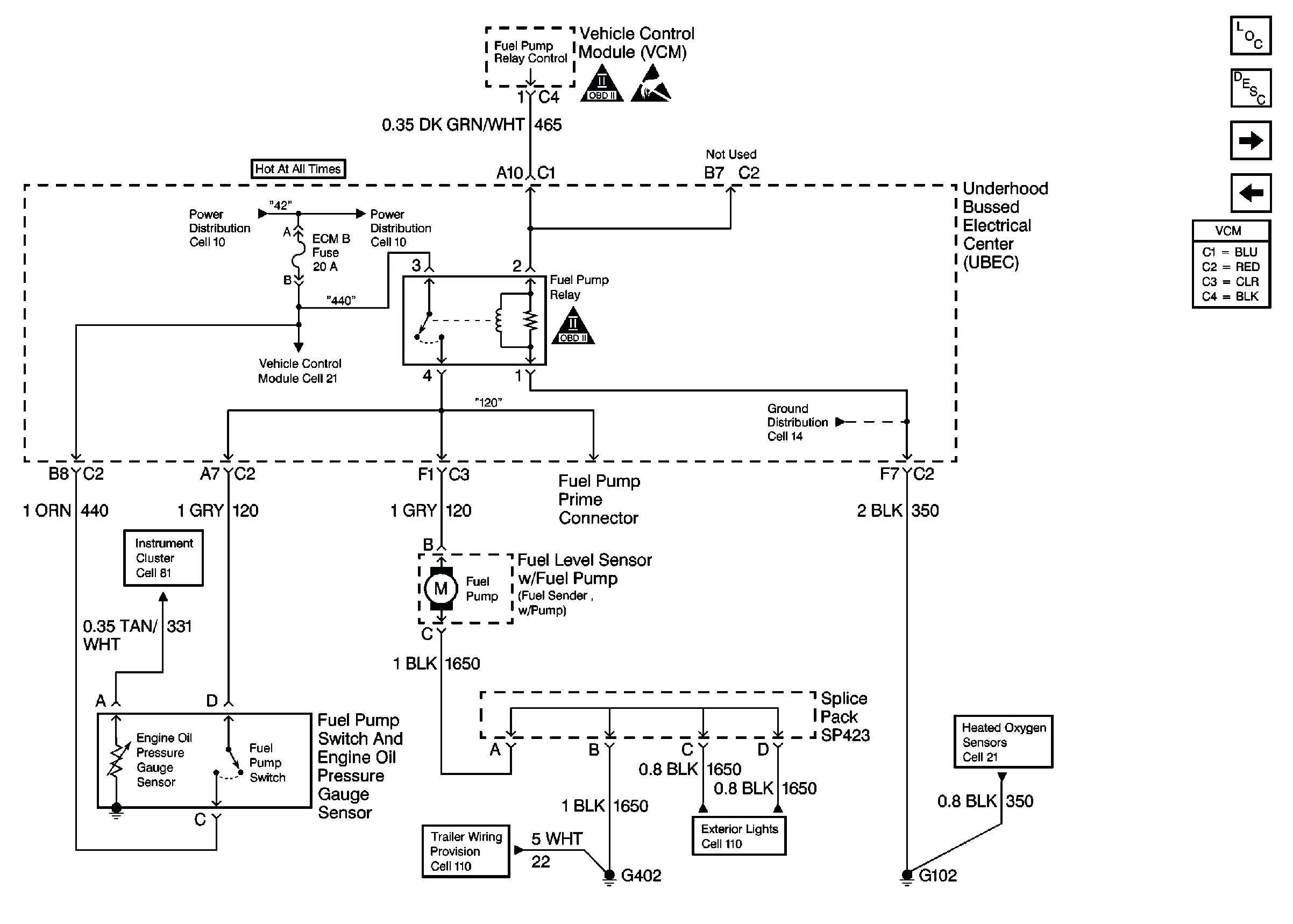
Your 4 wire oxygen sensor wiring diagram images are available in this site. 4 wire oxygen sensor wiring diagram are a topic that is being searched for and liked by netizens now. You can Find and Download the 4 wire oxygen sensor wiring diagram files here. Get all royalty-free photos.
If you’re searching for 4 wire oxygen sensor wiring diagram pictures information linked to the 4 wire oxygen sensor wiring diagram topic, you have visit the ideal blog. Our site always gives you suggestions for downloading the maximum quality video and image content, please kindly surf and find more informative video content and images that fit your interests.
4 Wire Oxygen Sensor Wiring Diagram. Home decorating style 2022 for 4 wire o2 sensor wiring diagram bmw, you can see 4 wire o2 sensor wiring diagram bmw and more pictures for home interior designing 2022 318292 at resume example ideas. Two wires are for the heated circuit and the other two wires are for sensing elements. In the case i was called in on the vehicle was a 2000 jeep grand cherokee with the 4 0l engine. Variety of 4 wire oxygen sensor wiring diagram.
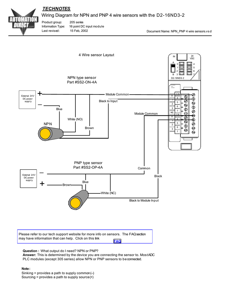
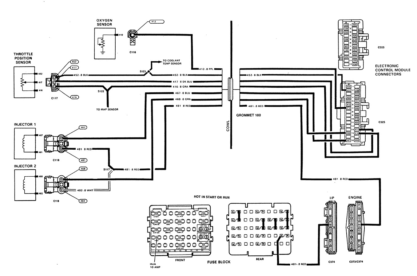
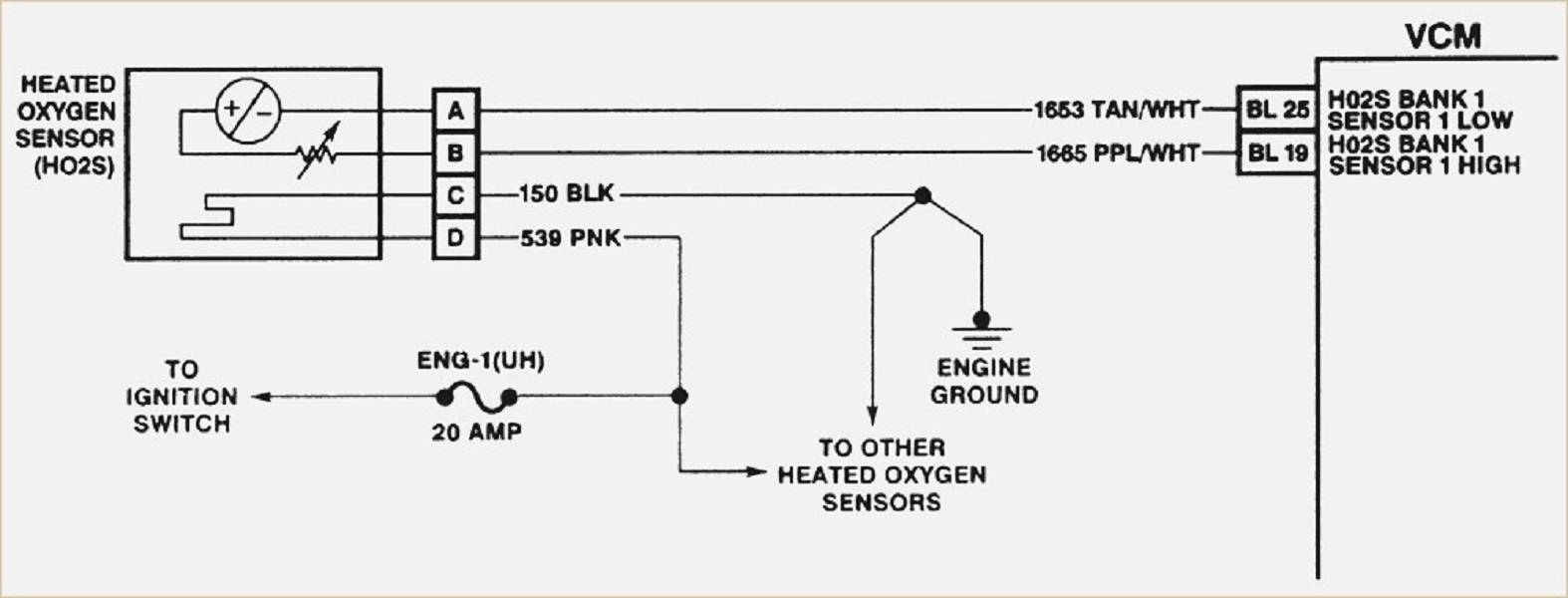 4 Wire O2 Sensor Wiring Diagram Cadician�s Blog From 2020cadillac.com
Bosch oxygen sensor wiring diagram. The other thing which you will come across a circuit diagram could be traces. It contains directions and diagrams for different types of wiring methods and other products like lights, home windows, and so forth. Figure d 2 the dissolved oxygen sensor wiring diagram scientific. According to previous, the lines in a 4 wire oxygen sensor wiring diagram represents wires. Cut the wiring of oe sensor 4″ from end of connector as illustrated.
Lay the bosch universal oxygen sensor beside the oe sensor and cut the bosch universal oxygen sensor wiring to the length of the oe sensor, but do not cut to less than 5″ (hex/flange face to end of sensor wire).
4 wire o2 sensor wiring diagram downstream dodge. All wires are intact but i just can t figure out which goes where. The other thing which you will come across a circuit diagram could be traces. Oxygen sensor wiring diagram ford to properly read a electrical wiring diagram, one offers to learn how the particular components in the system operate. According to previous, the lines in a 4 wire oxygen sensor wiring diagram represents wires. The new sensor with the old connector must be the same length as the old sensor and.
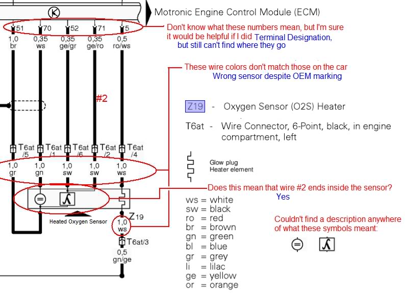 Source: wiring.hpricorpcom.com
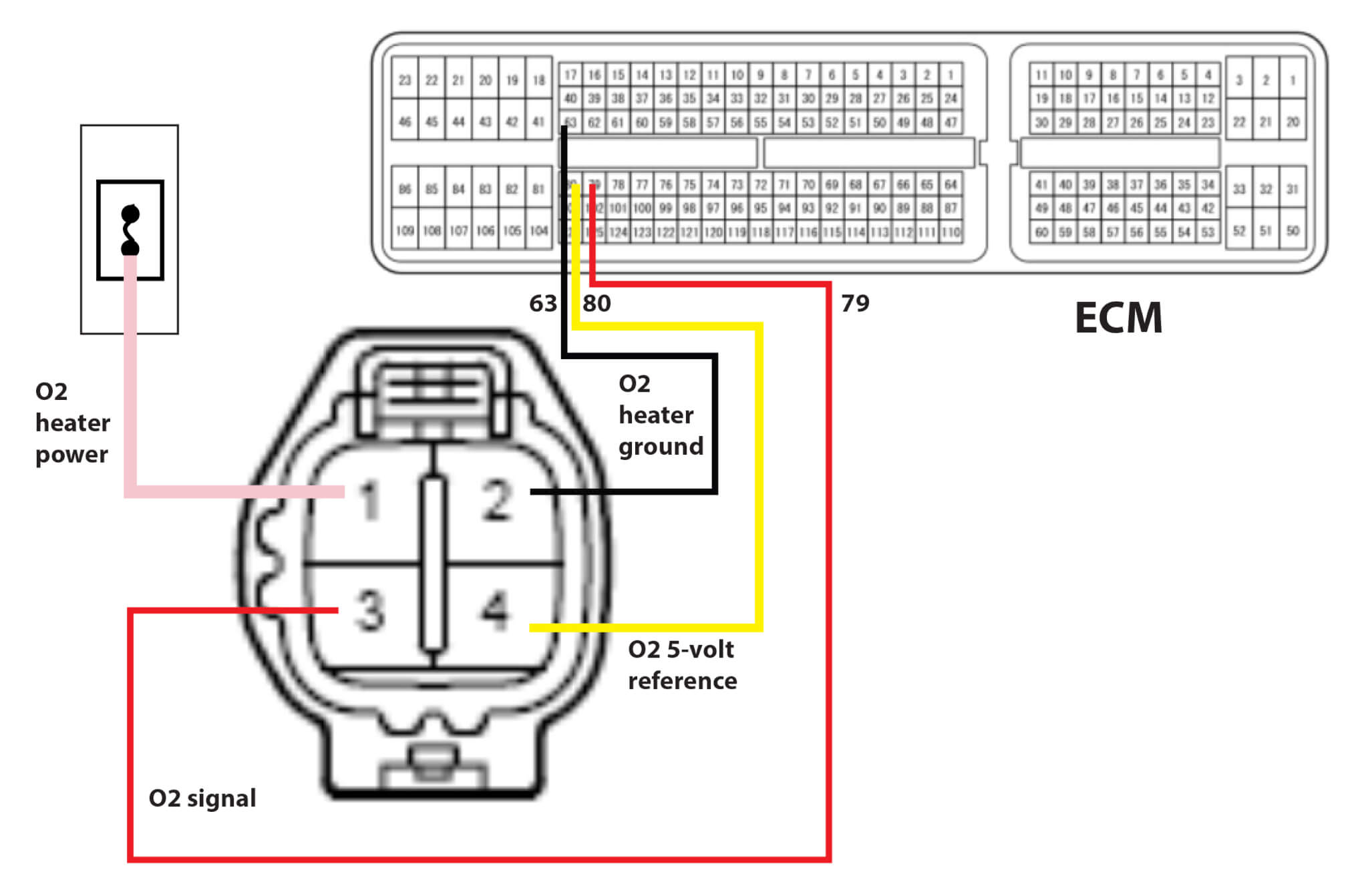
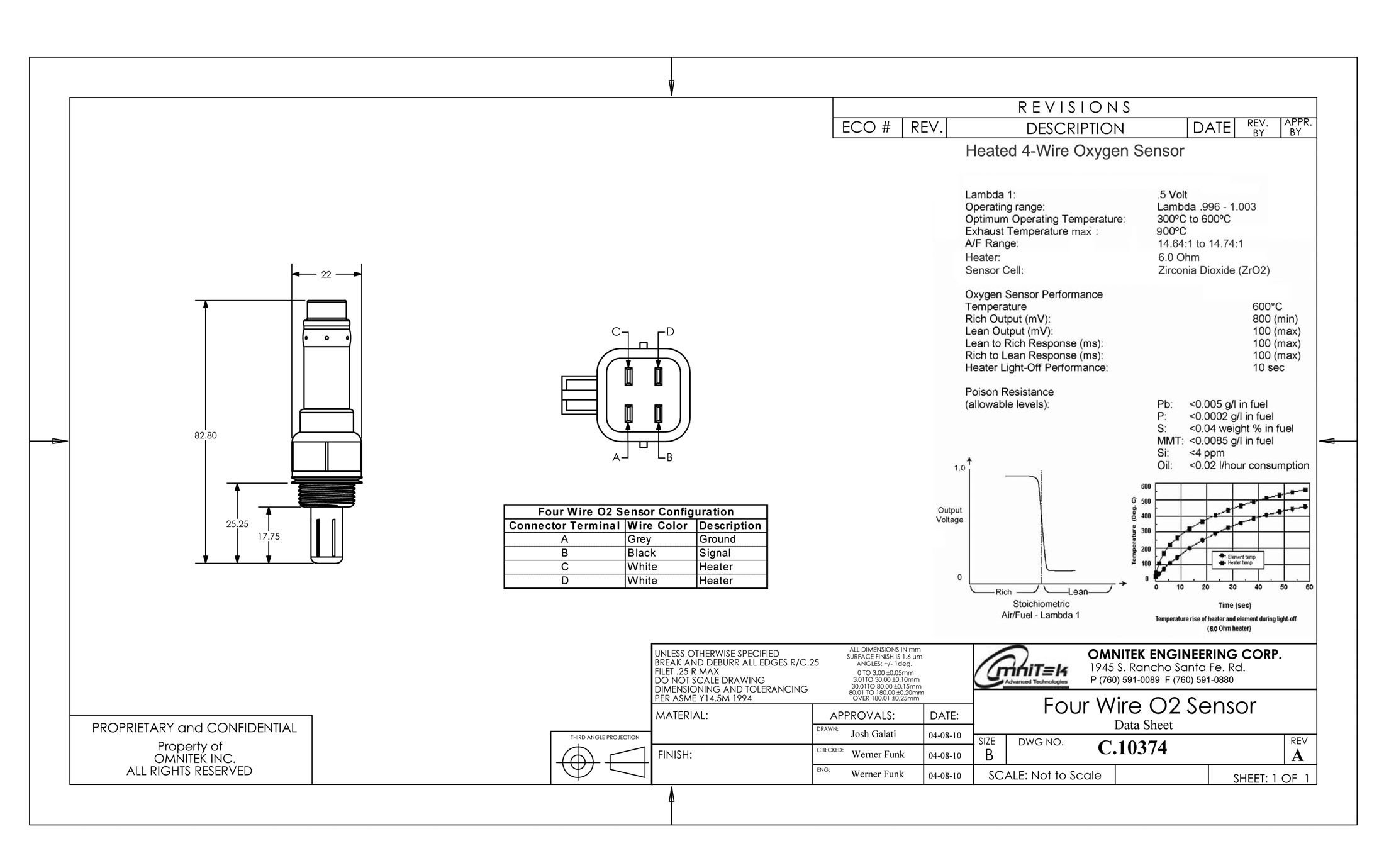
Cut the new sensor wires to length. A zirconium bulb is placed on. You’ll be in a position to understand exactly if the tasks needs to be accomplished, which makes it much simpler to suit your needs to correctly manage your time. You will need the wiring diagram for the car the oxygen sensor has 4 wires two white which are the heater one positive one negative it doesn�t matter which is which the black is ground the gray is the signal wire some have a blue wire black is always ground the blue would be sensor hope this helps This sensor measures the amount of unburned oxygen that is present in the oxygen as it exits the vehicle which is indicative of the fuel mixture.
 Source: ricardolevinsmorales.com
Hyundai accent wiring diagram and 0900c15280073b4f with golf cart hyundai accent hyundai hyundai cars. 4 wire o2 sensor wiring diagram civic 03 caravan bosch honda testing the oxygen sensor 1 heater 2002 2003 2 5l nissan altima eccpp oxygen sensor fits 13675 4 wires replacement o2 downstream for 2002 2006 nissan altima 2 5l automotive wire to o. A 4 wire oxygen sensor wiring diagram is also called a universal o2 sensor wiring diagram. A wiring diagram is a streamlined standard pictorial depiction of an electrical circuit. Two wires are for the heated circuit and the other two wires are for sensing elements.
 Source: dentistmitcham.com
It reveals the components of the circuit as streamlined forms, and also the power as well as signal links between the tools. I searched high and low for this video. Automotive engines are composed of a complex set of systems that are monitored by several types of sensors. You will need the wiring diagram for the car the oxygen sensor has 4 wires two white which are the heater one positive one negative it doesn�t matter which is which the black is ground the gray is the signal wire some have a blue wire black is always ground the blue would be sensor hope this helps All wires are intact but i just can t figure out which goes where.
 Source: wwv.festivaldellafelicita.it
But, it doesn’t imply link between the cables. With infuriating to remove, replace or fix the wiring in an automobile, having an accurate and detailed 02 sensor 4 wire o2 sensor wiring. 4 wire oxygen sensor wiring diagram. Bosch oxygen sensor wiring diagram. 4 wire o2 sensor wiring diagram civic 03 caravan bosch honda testing the oxygen sensor 1 heater 2002 2003 2 5l nissan altima eccpp oxygen sensor fits 13675 4 wires replacement o2 downstream for 2002 2006 nissan altima 2 5l automotive wire to o.
 Source: wiring.hpricorpcom.com
I recently installed an obx header, purchased through ebay for $ delivered, on my miata (including a new single wire o2 sensor). 4 wire oxygen sensor wiring diagram wiring diagram is a simplified tolerable pictorial representation of an electrical circuit. A zirconium bulb is placed on. Abs system diagram in 2021 bmw e46 car fuses bmw This harness is designed to be a complete wiring harness for the fuel injection system on general motors 2005 2007 ls2 60l 24x fuel injected engines with drive by wire throttle.
Source: diagramportal.blogspot.com
Automotive engines are composed of a complex set of systems that are monitored by several types of sensors. Variety of 4 wire oxygen sensor wiring diagram. The other thing which you will come across a circuit diagram could be traces. Bank 1 is located on the passenger side of the engine compartment. Home decorating style 2022 for 4 wire oxygen sensor wiring diagram, you can see 4 wire oxygen sensor wiring diagram and more pictures for home interior designing 2022 318300 at resume example ideas.
 Source: pinterest.com
Figure d 2 the dissolved oxygen sensor wiring diagram scientific. For instance , if a module is usually powered up and it sends out a new signal of half the voltage and the technician will not know this, he would think he has a challenge, as he would expect the 12v. Two wires are for the heated circuit and the other two wires are for sensing elements. The new sensor with the old connector must be the same length as the old sensor and. It reveals the components of the circuit as streamlined forms, and also the power as well as signal links between the tools.
 Source: 2020cadillac.com
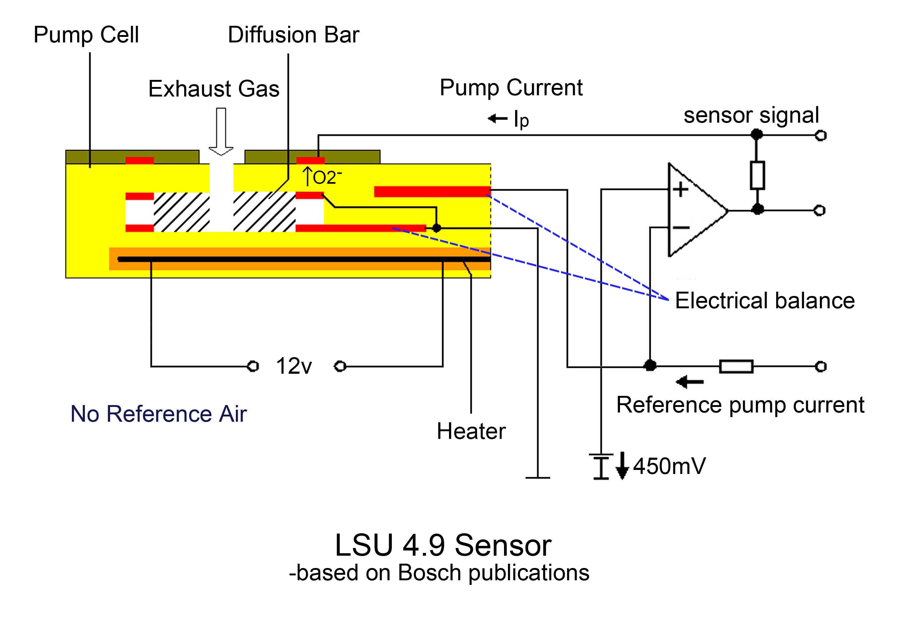
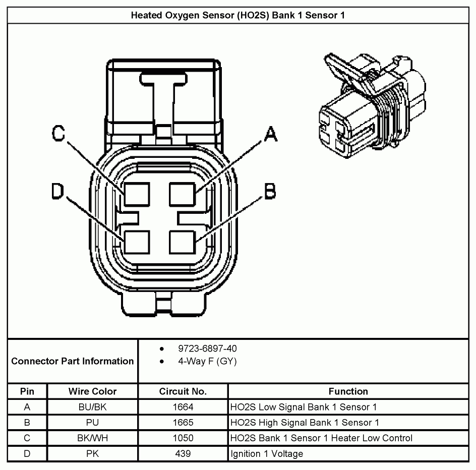
The sensing element wires go to the pcm, in which one wire is signal ground and the second wire is signal voltage. For instance , if a module is usually powered up and it sends out a new signal of half the voltage and the technician will not know this, he would think he has a challenge, as he would expect the 12v. Dissolved oxygen sensor wiring diagram o2 diagrams universal advanced diagnostics tracing ford truck 02 wires what to splice circuit and how section 4 2 wide band honda tech hyundai accent heated. Variety of 4 wire oxygen sensor wiring diagram. Automotive engines are composed of a complex set of systems that are monitored by several types of sensors.
 Source: dreamer-angel-tattoo.blogspot.com
Automotive engines are composed of a complex set of systems that are monitored by several types of sensors. This sensor measures the amount of unburned oxygen that is present in the oxygen as it exits the vehicle, which is indicative of the fuel mixture. 4 wire o2 sensor wiring diagram civic 03 caravan bosch honda testing the oxygen sensor 1 heater 2002 2003 2 5l nissan altima eccpp oxygen sensor fits 13675 4 wires replacement o2 downstream for 2002 2006 nissan altima 2 5l automotive wire to o. They work by producing their very own voltage by getting hot. Oxygen sensor wiring diagram ford to properly read a electrical wiring diagram, one offers to learn how the particular components in the system operate.
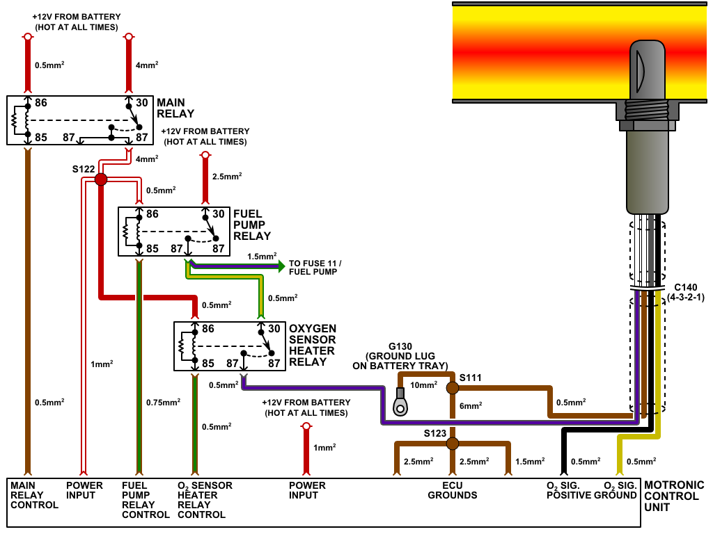
 Source: schematron.org
O2 sensor wiring diagram.this little pic is the wire side of the primary o2 sensor plug. Toyota 4 wire o2 sensor wiring diagram to properly read a electrical wiring diagram, one offers to learn how the particular components in the system operate. A wiring diagram is a streamlined standard pictorial depiction of an electrical circuit. 4 wire o2 sensor wiring diagram civic 03 caravan bosch honda testing the oxygen sensor 1 heater 2002 2003 2 5l nissan altima eccpp oxygen sensor fits 13675 4 wires replacement o2 downstream for 2002 2006 nissan altima 2 5l automotive wire to o. I recently installed an obx header, purchased through ebay for $ delivered, on my miata (including a new single wire o2 sensor).
 Source: dentistmitcham.com
Two wires are for the heated circuit and the other two wires are for sensing elements. Home decorating style 2022 for 4 wire o2 sensor wiring diagram bmw, you can see 4 wire o2 sensor wiring diagram bmw and more pictures for home interior designing 2022 318292 at resume example ideas. Injunction of two wires is generally indicated by black dot in the junction of two lines. All wires are intact but i just can t figure out which goes where. A 4 wire oxygen sensor wiring diagram is also called a universal o2 sensor wiring diagram.
 Source: wiringdiagram.2bitboer.com
For instance , if a module is usually powered up and it sends out a new signal of half the voltage and the technician will not know this, he would think he has a challenge, as he would expect the 12v signal. A 4 wire oxygen sensor wiring diagram is also called a universal o2 sensor wiring diagram. Figure d 2 the dissolved oxygen sensor wiring diagram scientific. 4 wire oxygen sensor wiring diagram. If playback doesn�t begin shortly, try restarting your device.
 Source: 2020cadillac.com
According to previous, the lines in a 4 wire oxygen sensor wiring diagram represents wires. In the case i was called in on the vehicle was a 2000 jeep grand cherokee with the 4 0l engine. Lay the bosch universal oxygen sensor beside the oe sensor and cut the bosch universal oxygen sensor wiring to the length of the oe sensor, but do not cut to less than 5″ (hex/flange face to end of sensor wire). This sensor measures the amount of unburned oxygen that is present in the oxygen as it exits the vehicle which is indicative of the fuel mixture. You’ll be in a position to understand exactly if the tasks needs to be accomplished, which makes it much simpler to suit your needs to correctly manage your time.
 Source: 2020cadillac.com
Oxygen sensor wiring diagram ford to properly read a electrical wiring diagram, one offers to learn how the particular components in the system operate. This harness is designed to be a complete wiring harness for the fuel injection system on general motors 2005 2007 ls2 60l 24x fuel injected engines with drive by wire throttle. But, it doesn’t imply link between the cables. In the case i was called in on the vehicle was a 2000 jeep grand cherokee with the 4 0l engine. The sensing element wires go to the pcm, in which one wire is signal ground and the second wire is signal voltage.
 Source: 2020cadillac.com
This sensor measures the amount of unburned oxygen that is present in the oxygen as it exits the vehicle, which is indicative of the fuel mixture. Abs system diagram in 2021 bmw e46 car fuses bmw For instance , if a module is usually powered up and it sends out a new signal of half the voltage and the technician will not know this, he would think he has a challenge, as he would expect the 12v. This sensor measures the amount of unburned oxygen that is present in the oxygen as it exits the vehicle, which is indicative of the fuel mixture. Bosch oxygen sensor wiring diagram.
 Source: schematron.org
The oxygen sensor with 4 wires is the most commonly used oxygen sensor. For instance , if a module is usually powered up and it sends out a new signal of half the voltage and the technician will not know this, he would think he has a challenge, as he would expect the 12v signal. All wires are intact but i just can t figure out which goes where. You will need the wiring diagram for the car the oxygen sensor has 4 wires two white which are the heater one positive one negative it doesn�t matter which is which the black is ground the gray is the signal wire some have a blue wire black is always ground the blue would be sensor hope this helps They work by producing their very own voltage by getting hot.
 Source: pinterest.ca
The new sensor with the old connector must be the same length as the old sensor and. Oxygen sensor testtools needed to perform these tests. 4 wire oxygen sensor wiring diagram. These wires serve to heat up the o2 sensor to bring it up to the o2 sensor signal gives an indication of oxygen content sensed by the probe. Home decorating style 2022 for 4 wire o2 sensor wiring diagram bmw, you can see 4 wire o2 sensor wiring diagram bmw and more pictures for home interior designing 2022 318292 at resume example ideas.
 Source: wiringall.com
Figure d 2 the dissolved oxygen sensor wiring diagram scientific. A zirconium bulb is placed on. Abs system diagram in 2021 bmw e46 car fuses bmw Bank 1 is located on the passenger side of the engine compartment. If playback doesn�t begin shortly, try restarting your device.
This site is an open community for users to share their favorite wallpapers on the internet, all images or pictures in this website are for personal wallpaper use only, it is stricly prohibited to use this wallpaper for commercial purposes, if you are the author and find this image is shared without your permission, please kindly raise a DMCA report to Us.
If you find this site beneficial, please support us by sharing this posts to your own social media accounts like Facebook, Instagram and so on or you can also save this blog page with the title 4 wire oxygen sensor wiring diagram by using Ctrl + D for devices a laptop with a Windows operating system or Command + D for laptops with an Apple operating system. If you use a smartphone, you can also use the drawer menu of the browser you are using. Whether it’s a Windows, Mac, iOS or Android operating system, you will still be able to bookmark this website.


