
Your 4 pole isolator wiring diagram images are ready. 4 pole isolator wiring diagram are a topic that is being searched for and liked by netizens today. You can Find and Download the 4 pole isolator wiring diagram files here. Download all royalty-free photos and vectors.
If you’re searching for 4 pole isolator wiring diagram pictures information connected with to the 4 pole isolator wiring diagram interest, you have come to the ideal site. Our website frequently provides you with hints for downloading the highest quality video and picture content, please kindly search and locate more informative video content and graphics that fit your interests.
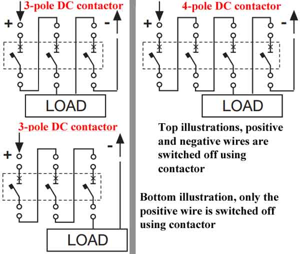
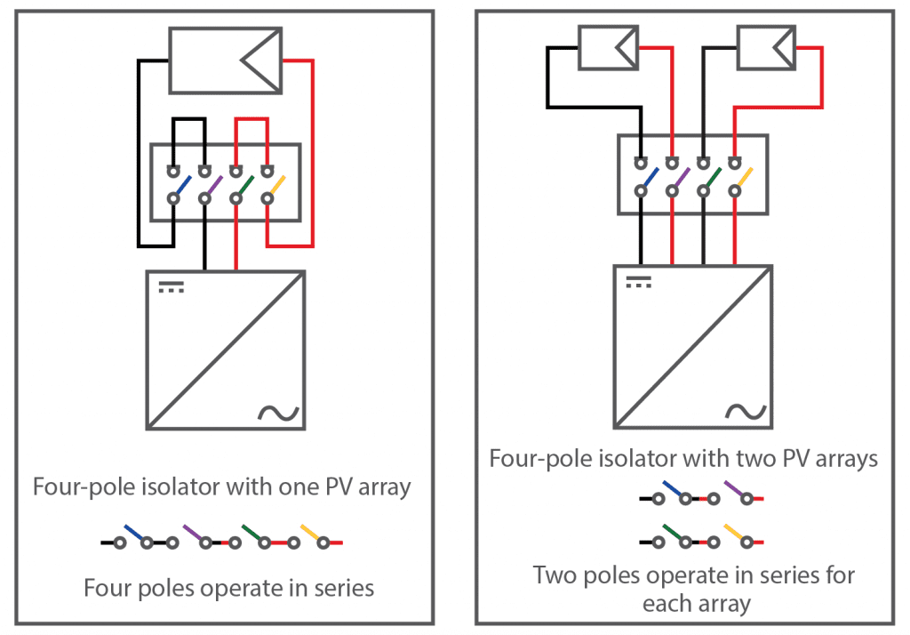
4 Pole Isolator Wiring Diagram. In the below mccb wiring diagram i show the complete method of wiring and installation of three pole molded case circuit breaker. Diagram changeover switch wiring diagram full version hd. Geyser switch wiring theop power solutions. Fisher 4 port isolation module wiring diagram wiring diagram is a simplified welcome pictorial representation of an electrical circuit it shows the components of the circuit as simplified shapes and the talent and signal links together with the devices.
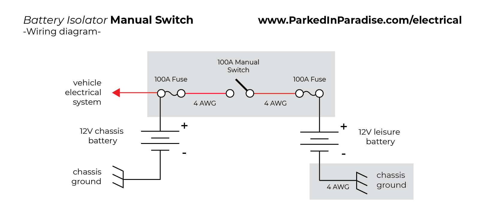
 4WaySwitch Battery Isolation Hellroaring Marine diagrams From hellroaring.com
4 pole isolator switch wiring diagram. Wrg 1835 2 pole 3 wire grounding diagram. Can be used as an emergency stop and can be locked in the off position using a padlock (not supplied). 4 6 1 4 8 12 3 7 11 14 (front view) 1 2 3 5 4 6 vehicle side (end view) (sockets) mvp blade to straight blade adapter kit pn 66760k pin no. How to wire a 2 pole isolator switch wiring diagram. How to install a double pole switch socketsandswitches com fan isolator wire 3 diynot forums electrical or isolation electrical4u geyser wiring theop power solutions home 2 mcb for single phase technical guide henley blocks and technique.
Free next day delivery available, free collection in 5.
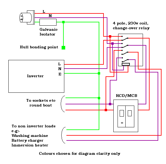
Switch to 1 and it will run either the generator or shore power if plugged in to our bus conversion and if i switch it to 2 and it runs the bus through our inverter and batteries and solar panels. How to install a fan isolator switch socketsandswitches com wire 3 pole diynot forums knightsbridge rounded edge 10a cl11bc at ukes double china dc1000v 32a 4 solar 63a siso electrical or isolation electrical4u geyser wiring theop power solutions wmps3pif hager uk three disconnector 630a lovato electric kg32bt204 gba007e kraus naimer panel mount non f. Blue sea acr wiring diagram electrical circuit sure power battery home electrical wiring boat wiring distribution house. Quickly and easily install a 4 way and 7 way. Fitting a 4pole 32a rotary isolation switch to act as an isolator in a twin and earth wiring single phase 16a circuit leading to an invertor. 1b circuit diagram for one pole of a 3 pole 4 way switch in.
 Source: wiring121.blogspot.com
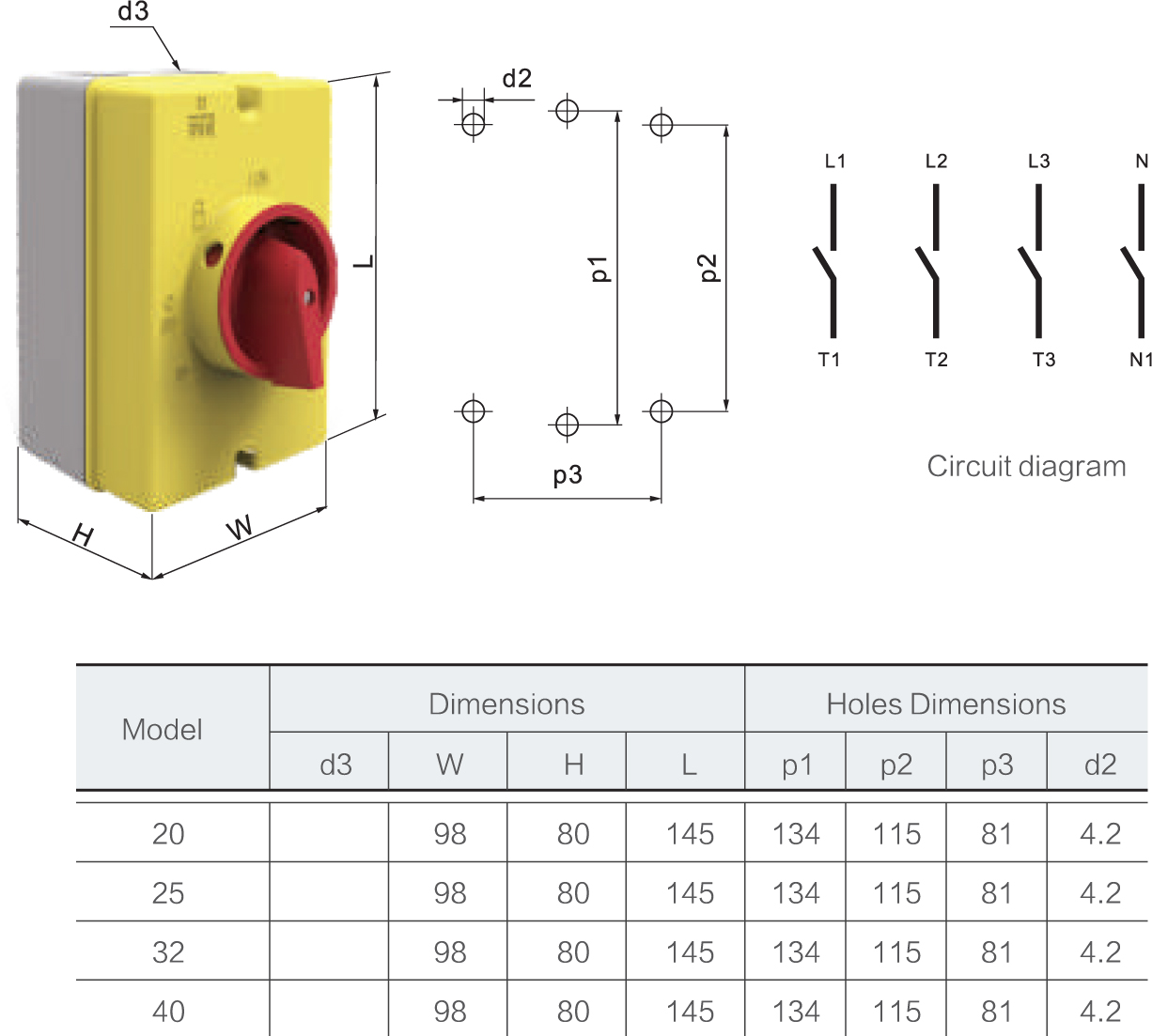
The isolator switch is obviously designed to switch 3 phase and neutral and. A wiring diagram usually gives instruction practically the relative slant and bargain of devices and terminals upon the devices to. Angelo on august 7, 2021. Esr 32a 3 pole 230v 415v medium ip65 rotary isolator electrical world. Switch is interlocked with the lid to prevent opening in the on position.
 Source: electrical4dummies.blogspot.com
Diagram napa fan switch wiring diagrams full version hd quality wiring diagrams ajaxdiagram reverbfestival it. Switch is interlocked with the lid to prevent opening in the on position. The isolator switch is obviously designed to switch 3 phase and neutral and. Diagram changeover switch wiring diagram full version hd. Can be used as an emergency stop and can be locked in the off position using a padlock (not supplied).
 Source: ukelectricalsupplies.com
Switch to 1 and it will run either the generator or shore power if plugged in to our bus conversion and if i switch it to 2 and it runs the bus through our inverter and batteries and solar panels. 4 pole 3 position rotary switch wiring diagram wiring diagram is a simplified agreeable pictorial representation of an electrical circuit. I have a 4 pole 32a rotary isolator switch which i am planning to use to isolate the supply to a hot tub. Style switching and other options. 07 november 1 2008 6 4 port 3 port isolation.
 Source: wiring121.blogspot.com
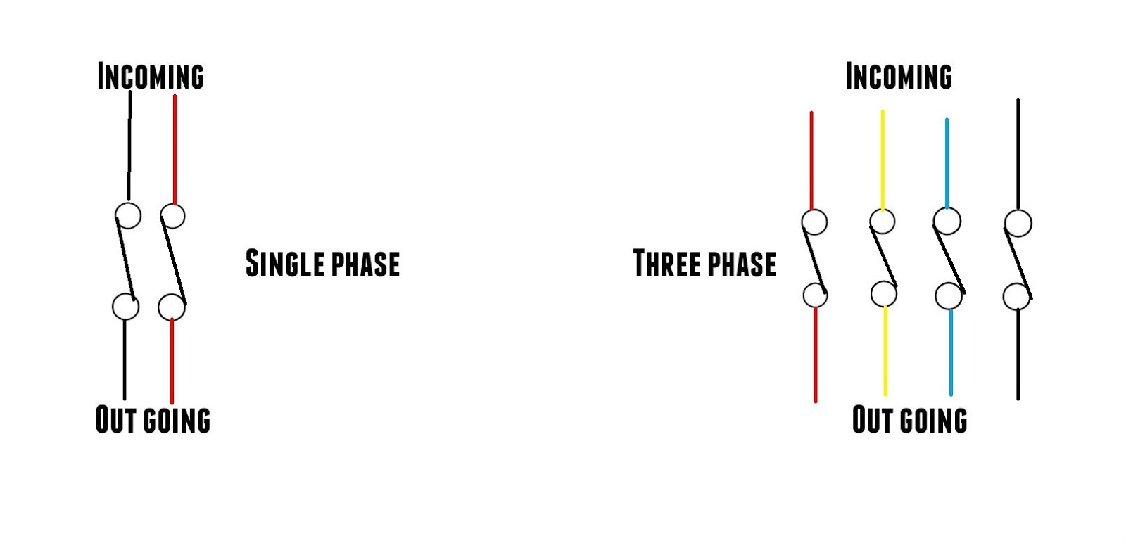
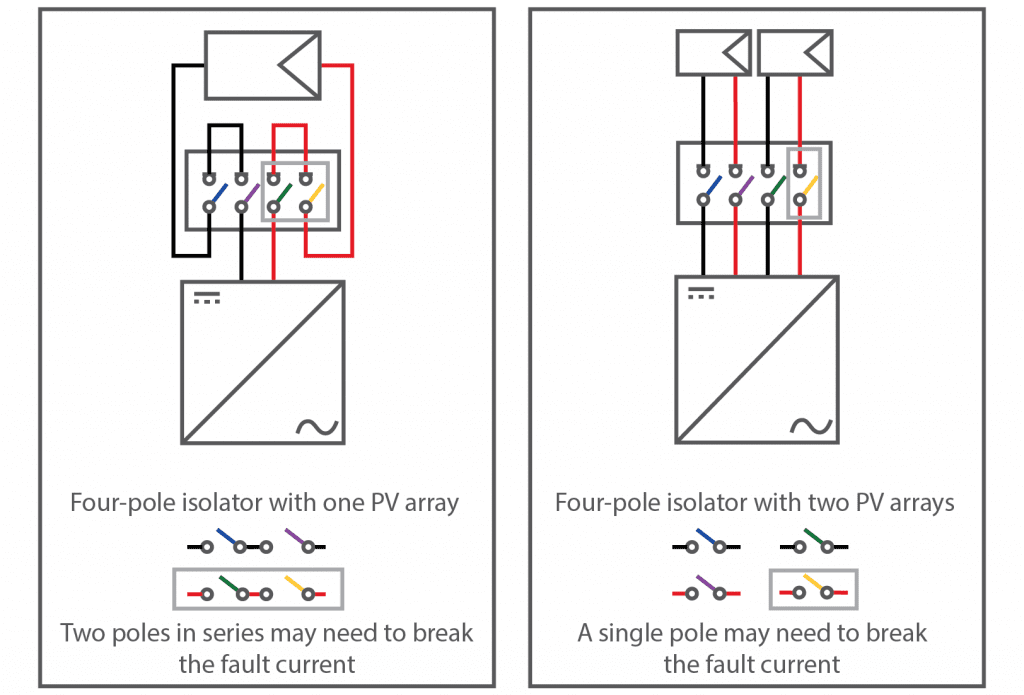
Can anyone tell me how to connect a 4 pole rotary isolator for use as a single pole isolator? Inside there are two earth connector fixings, and then on the top of the internal box are l1, l2 and l3 connector positions with t1, t2. Gewiss 16amp 3 pole rotary isolator isolators uk electrical supplies. The supplied switch (from screwfix) doesn�t have a wiring diagram. Schematic 4 pole starter solenoid wiring diagram.
 Source: wiring121.blogspot.com
Single alternator battery isolator wiring diagram boat wiring car alternator car audio installation. Fisher 4 port isolation module wiring diagram wiring diagram is a simplified welcome pictorial representation of an electrical circuit it shows the components of the circuit as simplified shapes and the talent and signal links together with the devices. A wiring diagram usually gives instruction practically the relative slant and bargain of devices and terminals upon the devices to. Europa 20amp 4 pole rotary isolator how to wire a 3 switch knightsbridge 32a 230v 415v ip65 non f isolators manualzz ac dc electricians forums hylec apl switches rounded edge 10a fan esr medium electrical isolation gewiss 32amp 2 position 63a 70 rt hp mk with padlock. Kg32bt204 gba007e kraus naimer 4 pole panel mount non f isolator switch 32 a maximum cur 11 kw power rating ip65 rs.
 Source: tonetastic.info
Electrical diagram brand on off bys dc isolator switches series rated operational voltage (dc poles) technical data ue symbol merit unit. I have a 4 pole 32a rotary isolator switch which i am planning to use to isolate the supply to a hot tub. Style switching and other options. It shows the components of the circuit as simplified shapes and the talent and signal connections together with the devices. Head straight to the main forums to chat by click here:

Schematic 4 pole starter solenoid wiring diagram. Head straight to the main forums to chat by click here: Bathroom lighting circuit with simple image eyagci com. In the below mccb wiring diagram i show the complete method of wiring and installation of three pole molded case circuit breaker. Diagram napa fan switch wiring diagrams full version hd quality wiring diagrams ajaxdiagram reverbfestival it.

Fisher 4 port isolation module wiring diagram wiring diagram is a simplified welcome pictorial representation of an electrical circuit it shows the components of the circuit as simplified shapes and the talent and signal links together with the devices. Bathroom lighting circuit with simple image eyagci com. It shows the parts of the circuit as simplified shapes, and also the power and signal connections between the devices. Diagram 3 pole light switch diagram full version hd quality switch diagram ajaxdiagram reverbfestival it. Because it must be emphasized within systems by various atss.

Diagram napa fan switch wiring diagrams full version hd quality wiring diagrams ajaxdiagram reverbfestival it. The supplied switch (from screwfix) doesn�t have a wiring diagram. Bathroom lighting circuit with simple image eyagci com. Electrical diagram brand on off bys dc isolator switches series rated operational voltage (dc poles) technical data ue symbol merit unit. Diagram 6 way wiring diagram full version hd quality wiring diagram radiatordiagram andreapendibene it.
 Source: wiring121.blogspot.com
30 automotive relay wiring diagram relay diagram electrical diagram. 4 6 1 4 8 12 3 7 11 14 (front view) 1 2 3 5 4 6 vehicle side (end view) (sockets) mvp blade to straight blade adapter kit pn 66760k pin no. If replacing an existing switch or cooker unit, always take careful note of the cables, then trim wires to approximate length to allow the. How to wire a db distribution board wiring. 1b circuit diagram for one pole of a 3 pole 4 way switch in.
 Source: chanish.org
4 pole solenoid wiring diagram wiring diagram is a simplified agreeable pictorial representation of an electrical circuit it shows the components of the circuit as simplified shapes and the knack and signal friends between the devices. Diagram changeover switch wiring diagram full version hd. 4 wire strobe light wiring diagram. Gewiss 16amp 3 pole rotary isolator isolators uk electrical supplies. 3 pole rotary isolator switch wiring diagram.
 Source: smartgauge.co.uk
Gewiss 16amp 3 pole rotary isolator isolators uk electrical supplies. Hi i am wiring a 32a 4 pole tp & n rotary isolator switch ip65 in line on my van and was wondering if all the terminals on the inside numbered 1 to 6 are seperate circuits ie 1 and 4 2 and 5 and 3 and six, the reason is i wired a live and a neutral on seperats circuits and put a tester on them and i was getting 12 volts coming from the live and about 4 volts coming from the neutral ????? A wiring diagram usually gives instruction practically the relative slant and bargain of devices and terminals upon the devices to. Inside there are two earth connector fixings, and then on the top of the internal box are l1, l2 and l3 connector positions with t1, t2. I have a 4 pole 32a rotary isolator switch which i am planning to use to isolate the supply to a hot tub.

Electrical isolator or isolation switch electrical4u. How to install a double pole switch fan isolator wire 3 electrical isolation geyser wiring theop power 2 mcb for single phase technical guide henley blocks and. Esr 32a 3 pole 230v 415v medium ip65 rotary isolator electrical world. Diagram changeover switch wiring diagram full version hd. 1b circuit diagram for one pole of a 3 pole 4 way switch in.
 Source: veti.co.za
Head straight to the main forums to chat by click here: Usually the 4th pole is marked with a big n, if not there is usually a little piece of paper that shows the correct method but like above just pick one of the 3 poles for l and used the 4th pole with the switching symbol as your n. The isolator switch is obviously designed to switch 3 phase and neutral and. Diagram napa fan switch wiring diagrams full version hd quality wiring diagrams ajaxdiagram reverbfestival it. Because it must be emphasized within systems by various atss.
 Source: wiring121.blogspot.com
In the below mccb wiring diagram i show the complete method of wiring and installation of three pole molded case circuit breaker. 4 port isolation module system adapter kits. Ac rotary switch dc1000v 4 pole solar dc isolator china made in com. How to install a fan isolator switch socketsandswitches com wire 3 pole diynot forums knightsbridge rounded edge 10a cl11bc at ukes double china dc1000v 32a 4 solar 63a siso electrical or isolation electrical4u geyser wiring theop power solutions wmps3pif hager uk three disconnector 630a lovato electric kg32bt204 gba007e kraus naimer panel mount non f. Do i wire the n to the n block next to the earth or through the swithched fourth phase?
 Source: wiring121.blogspot.com
Otherwise, the arrangement will not work as it should be. Gewiss 16amp 3 pole rotary isolator isolators uk electrical supplies. How to wire a db distribution board wiring. Head straight to the main forums to chat by click here: Fitting a 4pole 32a rotary isolation switch to act as an isolator in a twin and earth wiring single phase 16a circuit leading to an invertor.

4 port isolation module system adapter kits. Weatherproof switch ip66 20a 2 pole switches isolators voltex electrical. How to install a double pole switch fan isolator wire 3 electrical isolation geyser wiring theop power 2 mcb for single phase technical guide henley blocks and. Can anyone tell me how to connect a 4 pole rotary isolator for use as a single pole isolator? How to wire a db distribution board wiring.
 Source: wiring121.blogspot.com
Angelo on august 7, 2021. Household wiring diagram australia the home electrical wiring diagrams start from this main light switch wiring 3 way switch wiring electrical wiring diagram. Schematic 4 pole starter solenoid wiring diagram. The supply is fed from a 3 core 6mm2 swa cable. A wiring diagram usually gives instruction practically the relative slant and bargain of devices and terminals upon the devices to.
This site is an open community for users to do submittion their favorite wallpapers on the internet, all images or pictures in this website are for personal wallpaper use only, it is stricly prohibited to use this wallpaper for commercial purposes, if you are the author and find this image is shared without your permission, please kindly raise a DMCA report to Us.
If you find this site good, please support us by sharing this posts to your favorite social media accounts like Facebook, Instagram and so on or you can also bookmark this blog page with the title 4 pole isolator wiring diagram by using Ctrl + D for devices a laptop with a Windows operating system or Command + D for laptops with an Apple operating system. If you use a smartphone, you can also use the drawer menu of the browser you are using. Whether it’s a Windows, Mac, iOS or Android operating system, you will still be able to bookmark this website.


