Your 4 in 1 esc wiring diagram images are ready. 4 in 1 esc wiring diagram are a topic that is being searched for and liked by netizens today. You can Find and Download the 4 in 1 esc wiring diagram files here. Get all royalty-free vectors.
If you’re looking for 4 in 1 esc wiring diagram images information connected with to the 4 in 1 esc wiring diagram interest, you have pay a visit to the ideal blog. Our site frequently gives you suggestions for refferencing the highest quality video and image content, please kindly hunt and locate more informative video content and images that match your interests.
4 In 1 Esc Wiring Diagram. I really don�t know how esc fets are meant to be wired, but it looks odd that one motor. Wiring anniversary special edition racestar rev35a anniversary special edition racerstar rev35 35a blheli_s s 4 in 1 esc. Connect signal wire to esc of motor 1 here : At this point in my project, i�m more interested.
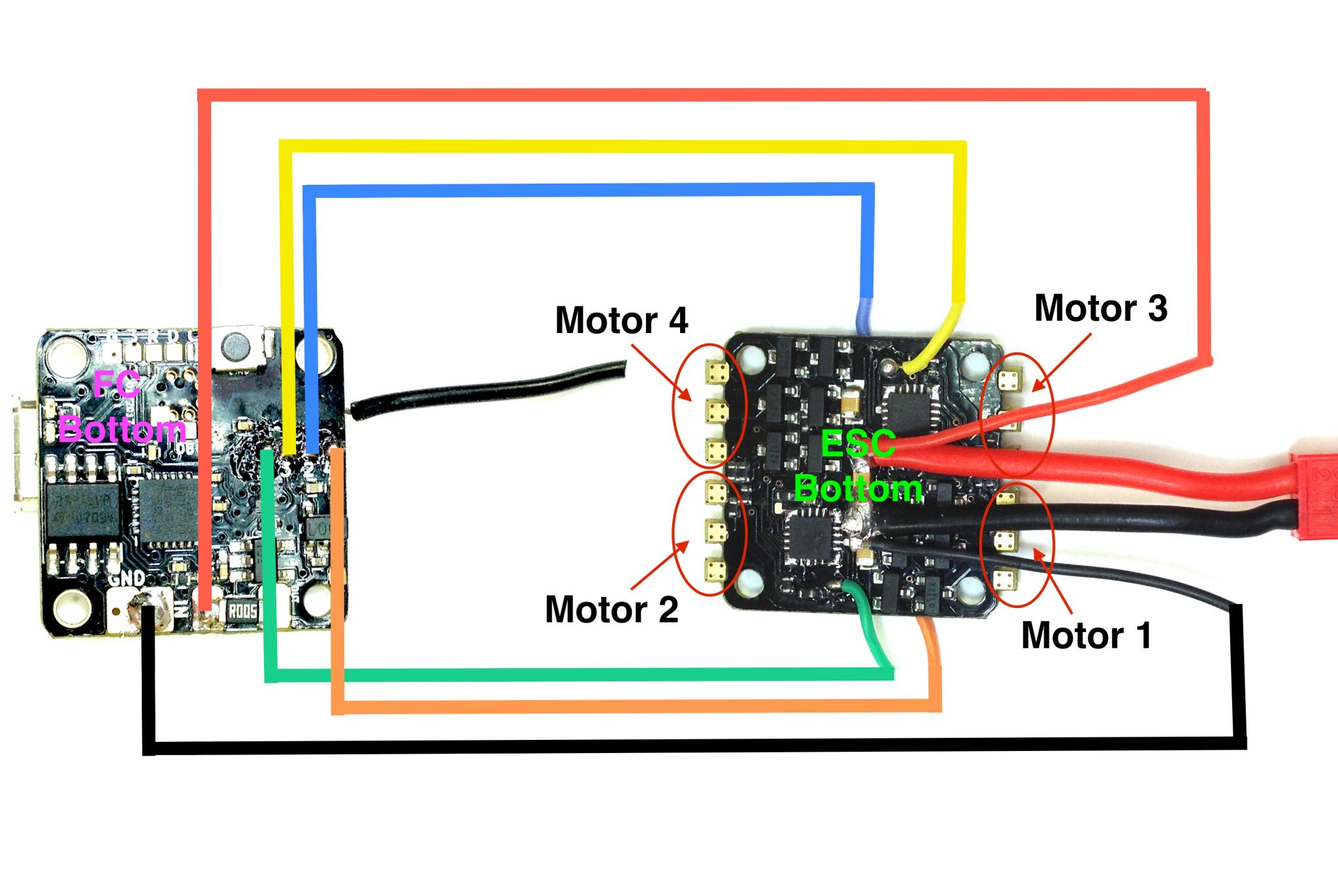 TinyFish FC and TinyPepper 1s 4A ESC wiring diagram Flex RC From flexrc.com
Omnibus f4 pro wiring diagram. Active 1 year, 1 month ago. When pairing the nano flight controller f4 with the hobbywing xrotor nano 4in1 esc, the wiring & installation can be very simple and easy. Bldc motor phases (3) 2. All the wire length above is the original length, not the length you see from the outside. If have any questions about drone wiring diagram please contact.
Connect signal wire to esc of motor 1 here :
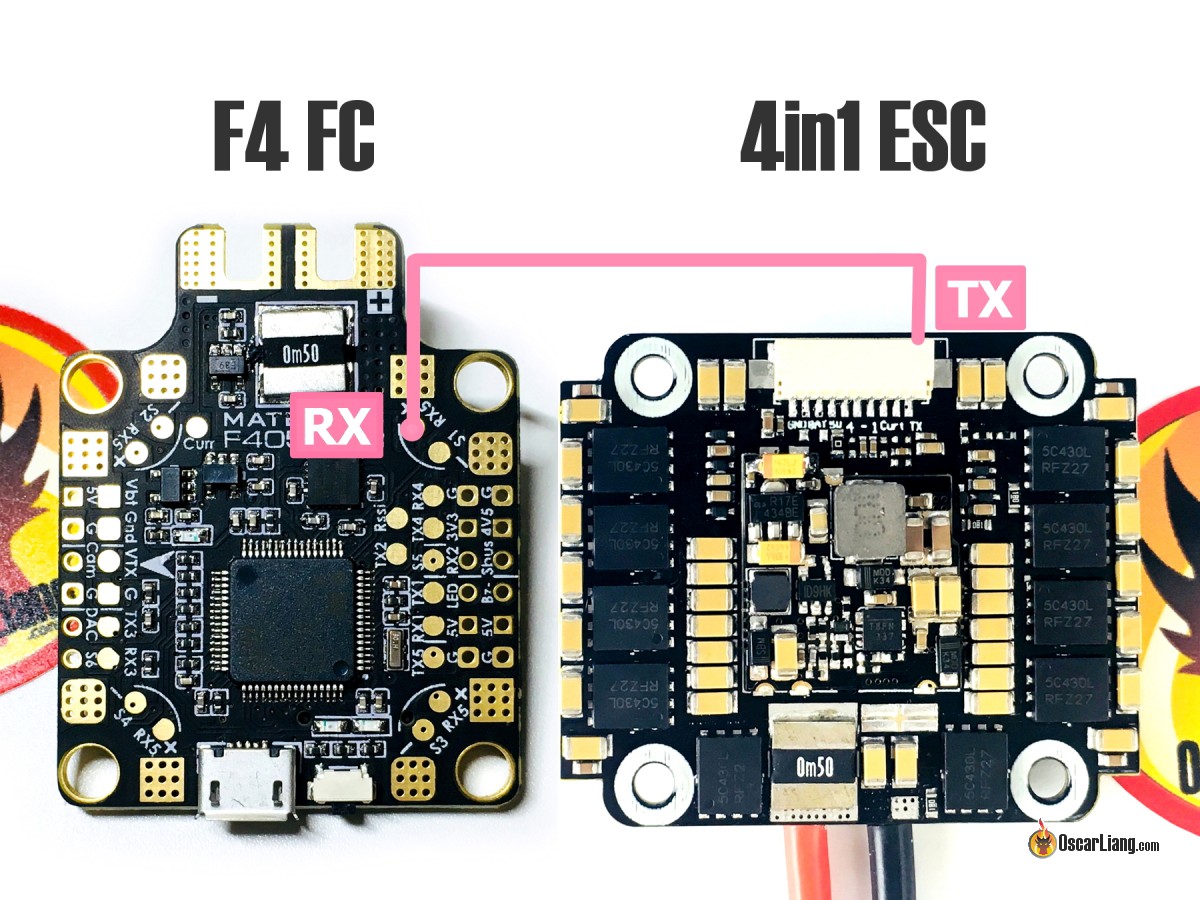
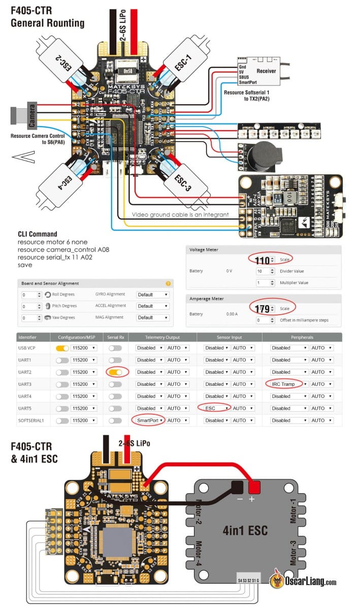
Before proceeding with installation of your kakute, you should complete as much of the. So to use the current sensor on the fc you need to connect the battery straight to it and then escs to the fc. For bit 4in1 esc that supports esc telemetry, there should be only 1 tx pin. Connect signal wire to esc of. Find your frame type below to determine the assigned order of the motors. A 4in1 esc is more convenient to use as there is less messy wiring as the powering of each esc is done internally on the board.
 Source: intofpv.com
The manual on hobbywing�s website isn�t very detailed. See note below for connection to pixhawk 4: Hobbywing xrotor smart audio wiring diagram. Wiring anniversary special edition racestar rev35a anniversary special edition racerstar rev35 35a blheli_s s 4 in 1 esc. Viewed 626 times 6 1 $\begingroup$ i have four brushless motors that i want to control using an arduino nano.
 Source: schematron.org
It supports current sensor and esc telemetry which has become a standard in blheli_32 esc. 4 in 1 esc wiring diagram. A 4in1 esc is more convenient to use as there is less messy wiring as the powering of each esc is done internally on the board. Find your frame type below to determine the assigned order of the motors. As you can see in the bottom right, i have not yet shown the wires connecting the (4in1) esc to the pixhawk 4 as i�m can�t work out which wire coming out of the esc goes where.
 Source: schematron.org
In this diagram the battery pads are pointed towards the back. As you can see in the bottom right, i have not yet shown the wires connecting the (4in1) esc to the pixhawk 4 as i�m can�t work out which wire coming out of the esc goes where. Bldc motor phases (3) 2. All the wire length above is the original length, not the length you see from the outside. A 4in1 esc is more convenient to use as there is less messy wiring as the powering of each esc is done internally on the board.
 Source: diagramweb.net
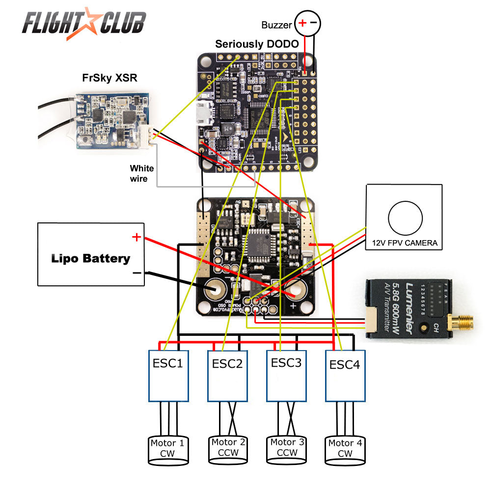
Connect the esc for motor 1 to the pdb pins marked m1 motor 6 s esc to the pins marked m6 etc. In this diagram the battery pads are pointed towards the back. If have any questions about drone wiring diagram please contact. When using a millivolt v2 ,. Just created this wiring diagram for my new build and mostly just have a question about wiring in regards to the 4 in 1 esc and the motors.
 Source: schematron.org
Just created this wiring diagram for my new build and mostly just have a question about wiring in regards to the 4 in 1 esc and the motors. Before proceeding with installation of your kakute, you should complete as much of the. It supports current sensor and esc telemetry which has become a standard in blheli_32 esc. Connect signal wire to esc of. This is a trade off between risk and.
 Source: diagramweb.net
Connect signal wire to esc of motor 4 here: When using a millivolt v2 ,. In this diagram the battery pads are pointed towards the back. So to use the current sensor on the fc you need to connect the battery straight to it and then escs to the fc. Typical connections on a 4in1 esc.
 Source: diagramweb.net
However damaging one of the esc’s means the retirement of the whole board. It supports current sensor and esc telemetry which has become a standard in blheli_32 esc. I really don�t know how esc fets are meant to be wired, but it looks odd that one motor. In this diagram the battery pads are pointed towards the back. Before proceeding with installation of your kakute, you should complete as much of the.
 Source: schematron.org
At this point in my project, i�m more interested. Connect signal wire to esc of motor 2 here: This is a trade off between risk and. When pairing the nano flight controller f4 with the hobbywing xrotor nano 4in1 esc, the wiring & installation can be very simple and easy. Lipo power supply + 3.
 Source: flexrc.com
However damaging one of the esc’s means the retirement of the whole board. Bldc motor phases (3) 2. Omnibus f4 pro wiring diagram. As you can see in the bottom right, i have not yet shown the wires connecting the (4in1) esc to the pixhawk 4 as i�m can�t work out which wire coming out of the esc goes where. Viewed 626 times 6 1 $\begingroup$ i have four brushless motors that i want to control using an arduino nano.
 Source: schematron.org
When pairing the nano flight controller f4 with the hobbywing xrotor nano 4in1 esc, the wiring & installation can be very simple and easy. Omnibus f4 pro wiring diagram. At least shunt resistor current sensing, which is what i always see on fcs and escs. So to use the current sensor on the fc you need to connect the battery straight to it and then escs to the fc. The fc and 4in1 are the xilo stax f4 45a if it makes a difference.
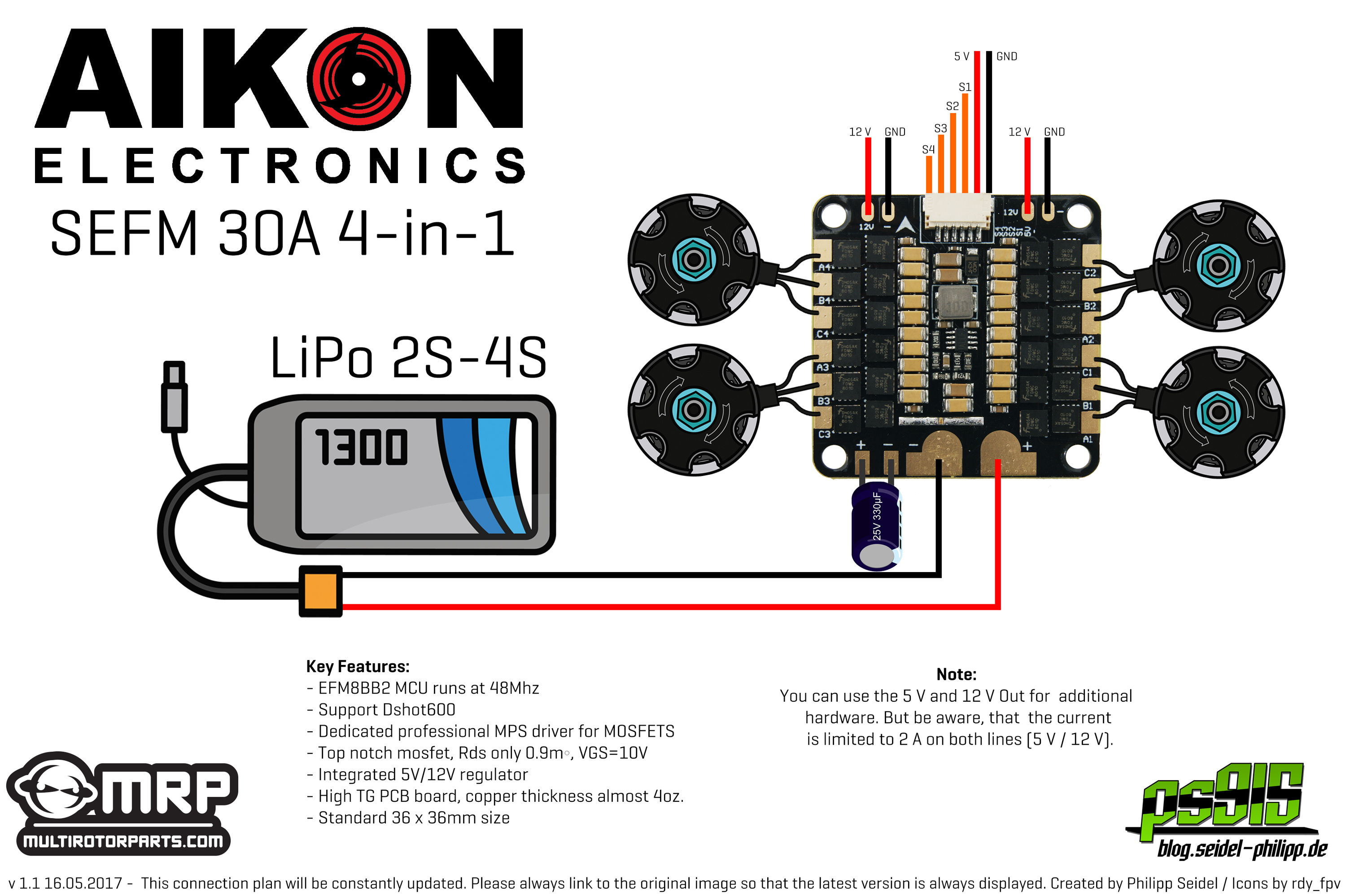
 Source: blog.seidel-philipp.de
So to use the current sensor on the fc you need to connect the battery straight to it and then escs to the fc. A 4in1 esc is more convenient to use as there is less messy wiring as the powering of each esc is done internally on the board. It supports current sensor and esc telemetry which has become a standard in blheli_32 esc. Today i hope to clear up any confusion i have created in wiring a 4 in 1 esc to your motors and flight controller. Hobbywing xrotor smart audio wiring diagram.
 Source: ori-fun-cosmetics.blogspot.com
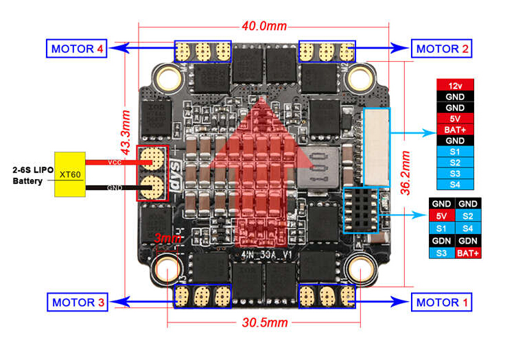
It supports current sensor and esc telemetry which has become a standard in blheli_32 esc. To connect the esc to your flight controller, most 4in1 esc uses a. At least shunt resistor current sensing, which is what i always see on fcs and escs. Connect signal wire to esc of motor 3 here: If have any questions about drone wiring diagram please contact.
 Source: multirotorguide.com
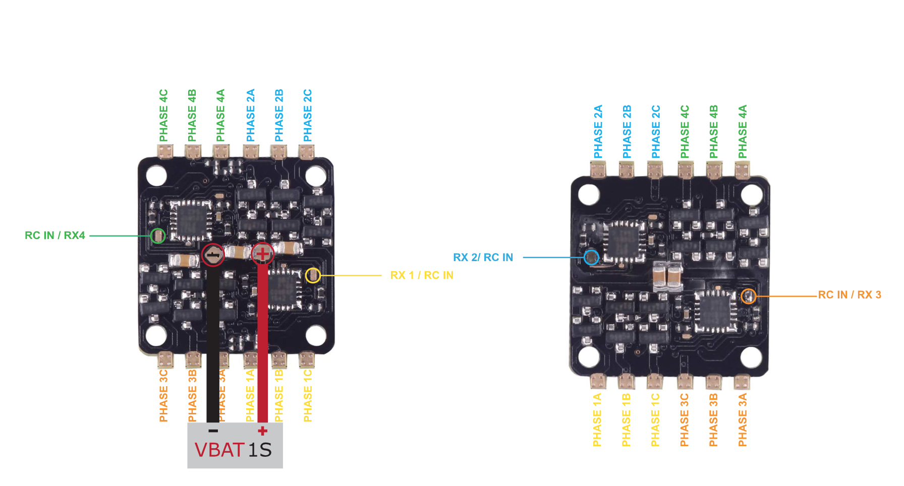
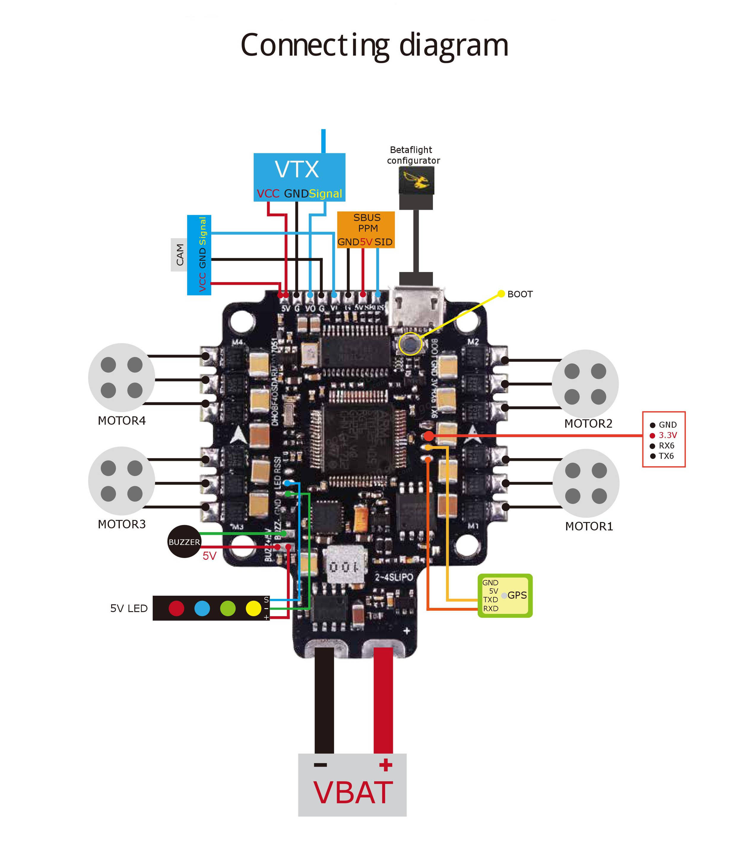
It supports current sensor and esc telemetry which has become a standard in blheli_32 esc. As you can see in the diagram above for a typhoon esc, there are 4 groups of 3 motor soldering tabs, so you would solder each motor to each group. When pairing the nano flight controller f4 with the hobbywing xrotor nano 4in1 esc, the wiring & installation can be very simple and easy. Connect signal wire to esc of motor 4 here: Radio calibration turn on the transmitter, move the throttle stick to the top position.
 Source: flyingtech.co.uk
As you can see in the diagram above for a typhoon esc, there are 4 groups of 3 motor soldering tabs, so you would solder each motor to each group. When using a millivolt v2 ,. It supports current sensor and esc telemetry which has become a standard in blheli_32 esc. Find your frame type below to determine the assigned order of the motors. Active 1 year, 1 month ago.
 Source: diagramweb.net
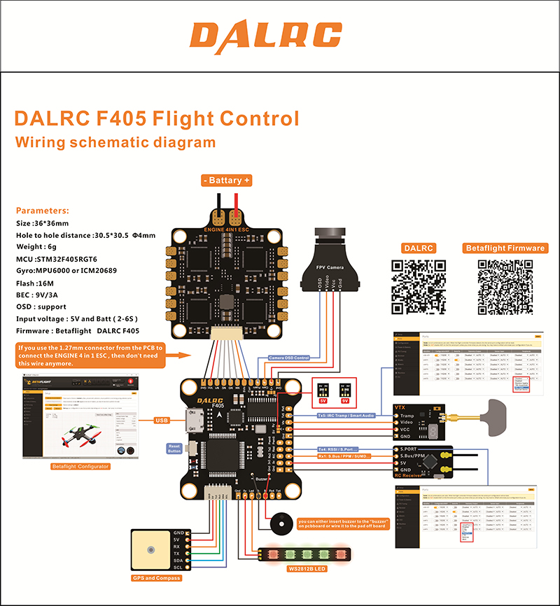
10cm, 10 wires, gnd, gnd, bat, 5v, pwm4, 3, 2, 1, current sensor, tx esc telemetry. As you can see in the diagram above for a typhoon esc, there are 4 groups of 3 motor soldering tabs, so you would solder each motor to each group. Wiring anniversary special edition racestar rev35a anniversary special edition racerstar rev35 35a blheli_s s 4 in 1 esc. The fc and 4in1 are the xilo stax f4 45a if it makes a difference. Then connect the signal wires from the pdb to the main output signal pins on the autopilot (ensuring that the motor order numbers match the main output pin numbers on the.

Lipo power supply + 3. When pairing the nano flight controller f4 with the hobbywing xrotor nano 4in1 esc, the wiring & installation can be very simple and easy. Omnibus f4 pro wiring diagram. The fc and 4in1 are the xilo stax f4 45a if it makes a difference. Bldc motor phases (3) 2.
 Source: schematron.org
However damaging one of the esc’s means the retirement of the whole board. Omnibus f4 pro wiring diagram. Connect signal wire to esc of motor 4 here: At least shunt resistor current sensing, which is what i always see on fcs and escs. Mobius bux i dont wanna lose it and 2.
 Source: aldeid.com
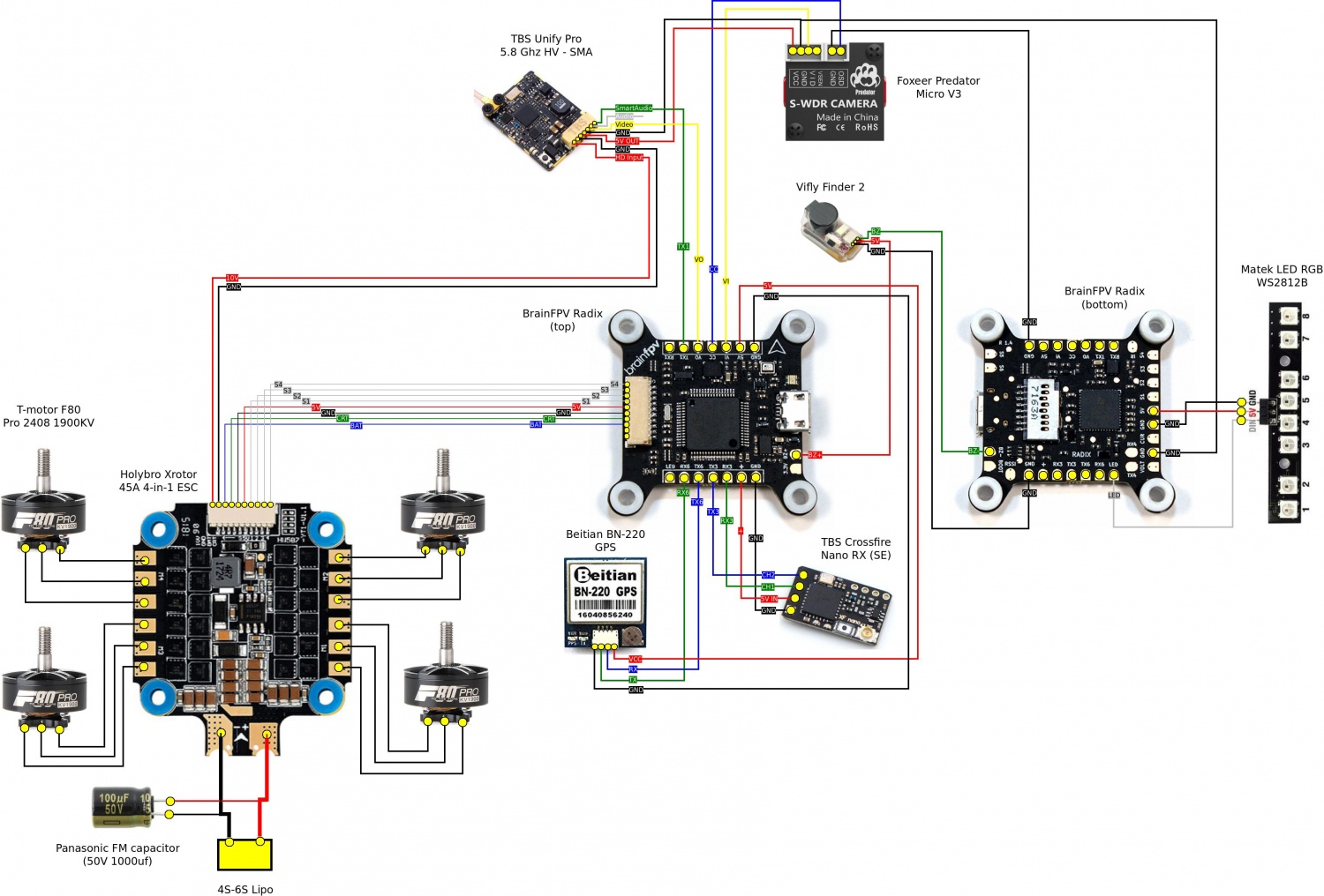
In this diagram the battery pads are pointed towards the back. Radio calibration turn on the transmitter, move the throttle stick to the top position. The term esc stands for “electronic speed control is an electronic circuit used to change the speed of an electric motor, its route, and also to perform as a dynamic brake. 10cm, 10 wires, gnd, gnd, bat, 5v, pwm4, 3, 2, 1, current sensor, tx esc telemetry. However damaging one of the esc’s means the retirement of the whole board.
This site is an open community for users to do sharing their favorite wallpapers on the internet, all images or pictures in this website are for personal wallpaper use only, it is stricly prohibited to use this wallpaper for commercial purposes, if you are the author and find this image is shared without your permission, please kindly raise a DMCA report to Us.
If you find this site value, please support us by sharing this posts to your own social media accounts like Facebook, Instagram and so on or you can also bookmark this blog page with the title 4 in 1 esc wiring diagram by using Ctrl + D for devices a laptop with a Windows operating system or Command + D for laptops with an Apple operating system. If you use a smartphone, you can also use the drawer menu of the browser you are using. Whether it’s a Windows, Mac, iOS or Android operating system, you will still be able to bookmark this website.


