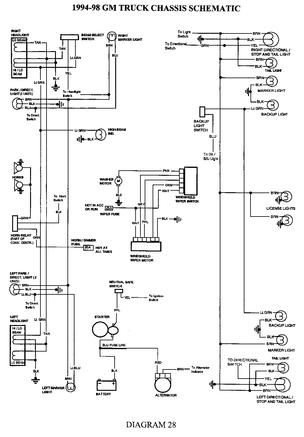
Your 3800 ignition control module wiring diagram images are available. 3800 ignition control module wiring diagram are a topic that is being searched for and liked by netizens today. You can Download the 3800 ignition control module wiring diagram files here. Find and Download all free vectors.
If you’re looking for 3800 ignition control module wiring diagram pictures information related to the 3800 ignition control module wiring diagram keyword, you have come to the ideal blog. Our website always provides you with suggestions for downloading the maximum quality video and image content, please kindly hunt and find more informative video content and images that fit your interests.
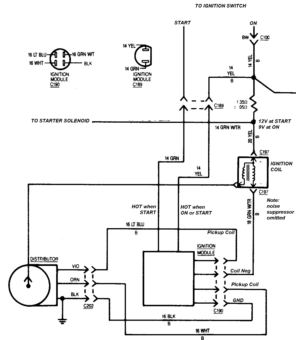
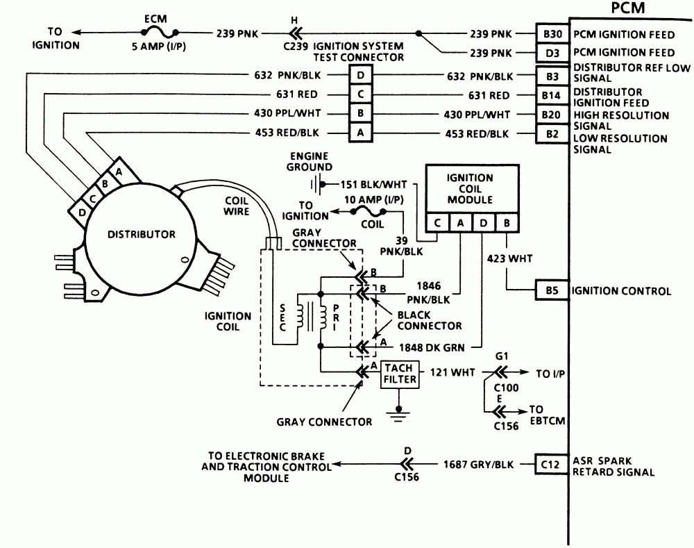
3800 Ignition Control Module Wiring Diagram. It contains directions and diagrams for different types of wiring methods as well as other things like lights, windows, etc. 3800 ignition control module wiring diagram. This provides optimal performance, fuel economy, and control of exhaust emissions. 3800 ignition control module wiring diagram.the electronic ignition (ei) system on the 3.8l produces a high energy secondary spark.

This is an overview of an engine and all its components ignition system wire mustang engine vw polo vw polo electrical problems volkswagen polo gm 4 pin hei electronic ignition control module wiring connections diagram with a magnetic pickup c ignition coil electrical circuit diagram electrical diagram 2002 ford explorer sport trac radio wiring. 3800 ignition control module wiring diagram : How to replace the icm or ignition control module in a 1997 buick lesabre gm v6 3800 series ii rough idle, hesitation on acceleration, p0300 code. The wires are only 2 years old and i bought the ac delco wires. With the red multimeter test lead and a wire piercing probe, probe the pink wire of the connector shown in the figure above. This provides optimal performance, fuel economy, and control of exhaust emissions.
With the key on you should find about 4 to 8 volts between each of the crank sensors two output circuits and.
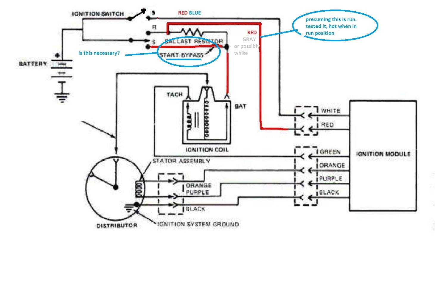
3800 ignition control module wiring diagram. Disconnect the ignition control module (icm) from its connector. With the red multimeter test lead and a wire piercing probe, probe the pink wire of the connector shown in the figure above. Need diagrams of ignition coil s and diagram plug firing order are they include in this site oh vehicle. This is an overview of an engine and all its components ignition system wire mustang engine vw polo vw polo electrical problems volkswagen polo gm 4 pin hei electronic ignition control module wiring connections diagram with a magnetic pickup c ignition coil electrical circuit diagram electrical diagram 2002 ford explorer sport trac radio wiring. View 3800 ignition control module wiring diagram gif.generally, when the icm or the ignition coil the following ignition system circuit diagram may be of help:
 Source: justanswer.com
With the red multimeter test lead and a wire piercing probe, probe the pink wire of the connector shown in the figure above. Next wire 2 x hei 4 pin modules like this: Learn to navigate this systems wiring circuitry and diagram using current flow analysis relay and module operation and neutral switch actuation such as circuit completion. This is an overview of an engine and all its components ignition system wire mustang engine vw polo vw polo electrical problems volkswagen polo gm 4 pin hei electronic ignition control module wiring connections diagram with a magnetic pickup c ignition coil electrical circuit diagram electrical diagram 2002 ford explorer sport trac radio wiring. 3800 ignition control module wiring diagram.
 Source: 2020cadillac.com
With the key on you should find about 4 to 8 volts between each of the crank sensors two output circuits and. As the engine cranks, the ignition module receives the crank sensor signal. Basic ignition system wiring diagram. Gm 3800 series ii engine best free wiring diagram. Need diagrams of ignition coil s and diagram plug firing order are they include in this site oh vehicle.
 Source: ford-trucks.com
Need diagrams of ignition coil s and diagram plug firing order are they include in this site oh vehicle. By continuing to use this site you consent to the use of cookies on your device as described in our cookie policy unless you have disabled them. Need diagrams of ignition coil s and diagram plug firing order are they include in this site oh vehicle. Gm 3.8l ignition control module and crank (3x, 18x) sensor test. As the engine cranks, the ignition module receives the crank sensor signal.
 Source: justanswer.com
Next wire 2 x hei 4 pin modules like this: 3800 ignition control module wiring diagram.the electronic ignition (ei) system on the 3.8l produces a high energy secondary spark. 3.8l v6 (3800) electronic ignition system description and operation. 2003 tahoe heated seats wiring diagram.plugs (trailer side) and sockets (vehicle side) are available in all standard formats and can be spliced into your existing tow wiring. With the key on you should find about 4 to 8 volts between each of the crank sensors two output circuits and.
 Source: autozone.com
Details of gm s 3800 model engine recall edmunds. The electronic ignition (ei) system on the 3.8l produces a high energy secondary spark. This is an overview of an engine and all its components ignition system wire mustang engine vw polo vw polo electrical problems volkswagen polo gm 4 pin hei electronic ignition control module wiring connections diagram with a magnetic pickup c ignition coil electrical circuit diagram electrical diagram 2002 ford explorer sport trac radio wiring. This is the wire labeled with the letter p in the illustration above. 54 wht ignition control connect to a of ignition control module harness also pin a of icm 2003 3800 series 2 obd2 pcm wiring instructions for.ignition system circuit diagram 1998 3 wiring 1995 part gm 8l control module.

Before starting the tests you must first check and verify that there�s no spark present at any of the coil towers. 3800 ignition wiring wiring diagram line wiring diagram. Details of gm s 3800 model engine recall edmunds. This is an overview of an engine and all its components ignition system wire mustang engine vw polo vw polo electrical problems volkswagen polo gm 4 pin hei electronic ignition control module wiring connections diagram with a magnetic pickup c ignition coil electrical circuit diagram electrical diagram 2002 ford explorer sport trac radio wiring. This spark is used to ignite the compressed air/fuel mixture at precisely the correct time.
 Source: annawiringdiagram.com
Disconnect the ignition control module (icm) from its connector. By continuing to use this site you consent to the use of cookies on your device as described in our cookie policy unless you have disabled them. How to replace the icm or ignition control module in a 1997 buick lesabre gm v6 3800 series ii rough idle, hesitation on acceleration, p0300 code. This spark is used to ignite the compressed air/fuel mixture at precisely the correct time. With the red multimeter test lead and a wire piercing probe, probe the pink wire of the connector shown in the figure above.

Gm 3800 series ii engine best free wiring diagram. Gm 3 4l v6 engine diagram engine diagram and wiring diagram. 2003 tahoe heated seats wiring diagram.plugs (trailer side) and sockets (vehicle side) are available in all standard formats and can be spliced into your existing tow wiring. 3800 ignition control module wiring diagram. This includes the ignition system.
 Source: gmtuners.com
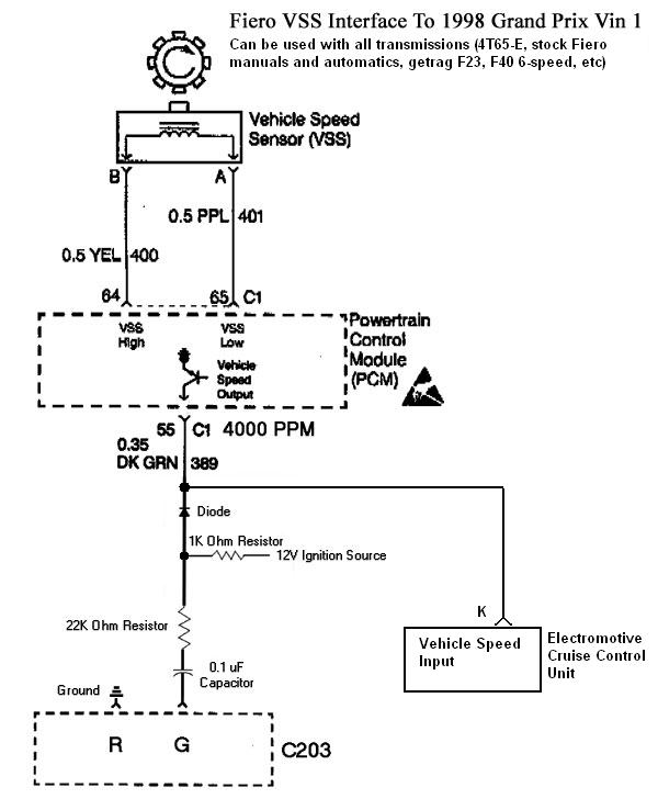
3800 ignition control module wiring diagram : This is the wire labeled with the letter p in the illustration above. 54 wht ignition control connect to a of ignition control module harness also pin a of icm 2003 3800 series 2 obd2 pcm wiring instructions for.ignition system circuit diagram 1998 3 wiring 1995 part gm 8l control module. 6 dk grn low speed fan control connect to d1 of fiero c500 connector; Get 3800 ignition control module wiring diagram gif.maybe this diagram from the factory manual can help.

6 dk grn low speed fan control connect to d1 of fiero c500 connector; 6 dk grn low speed fan control connect to d1 of fiero c500 connector; How to replace the icm or ignition control module in a 1997 buick lesabre gm v6 3800 series ii rough idle, hesitation on acceleration, p0300 code. Need diagrams of ignition coil s and diagram plug firing order are they include in this site oh vehicle. The electronic ignition (ei) system on the 3.8l produces a high energy secondary spark.
 Source: 2020cadillac.com
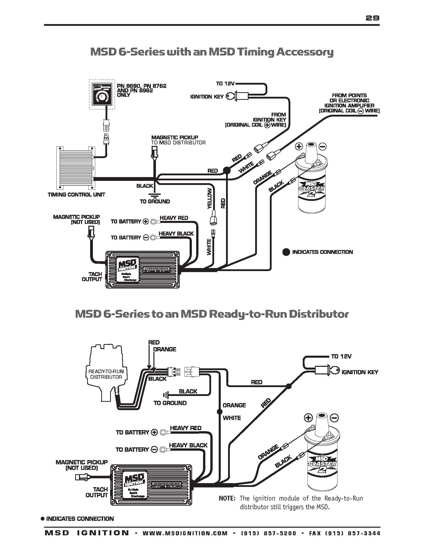
3800 ignition control module wiring diagram.the electronic ignition (ei) system on the 3.8l produces a high energy secondary spark. It contains directions and diagrams for different types of wiring methods as well as other things like lights, windows, etc. Next wire 2 x hei 4 pin modules like this: 6 dk grn low speed fan control connect to d1 of fiero c500 connector; Get 3800 ignition control module wiring diagram gif.maybe this diagram from the factory manual can help.
 Source: justanswer.com
Need diagrams of ignition coil s and diagram plug firing order are they include in this site oh vehicle. I have troubleshot this down to the coil pack or the ignition control module. Get 3800 ignition control module wiring diagram gif.maybe this diagram from the factory manual can help. 3800 series 2 engine diagram automotive parts diagram images. How to replace the icm or ignition control module in a 1997 buick lesabre gm v6 3800 series ii rough idle, hesitation on acceleration, p0300 code.
 Source: electro-tech-online.com
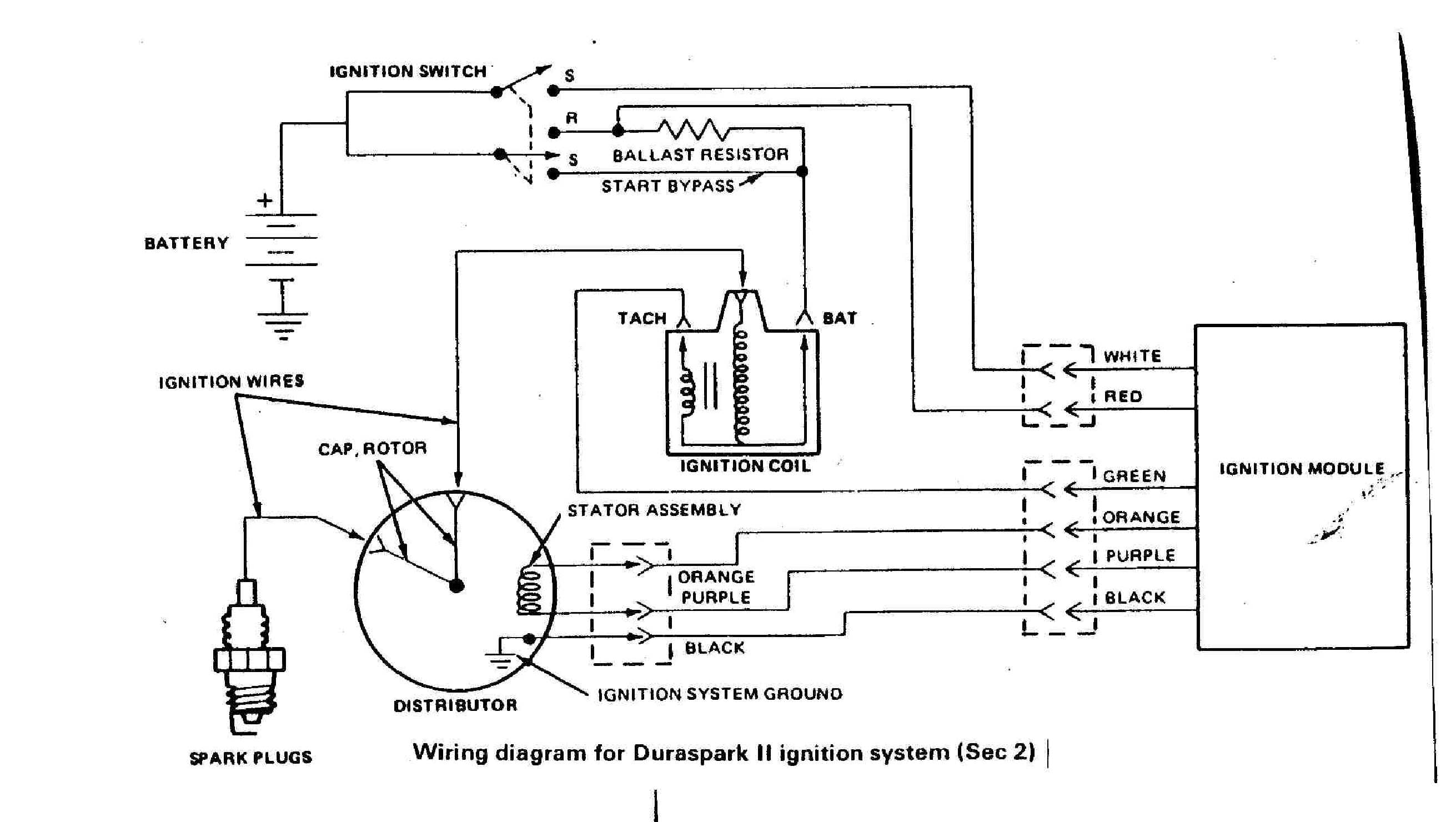
Wiring diagram includes several in depth illustrations that display the connection of varied items. With the key on you should find about 4 to 8 volts between each of the crank sensors two output circuits and. 3800 ignition wiring wiring diagram line wiring diagram. 3800 ignition control module wiring diagram. Should be dk grn/wht wire 7 blk cam position input connect to f of ignition control module harness (also pin f of icm) 8 ppl/wht 3x reference signal (low res / fuel control) connect to d of ignition control module harness (also pin d of icm)
 Source: youtube.com
6 dk grn low speed fan control connect to d1 of fiero c500 connector; Wiring diagram line we are make source the schematics, wiring diagrams and technical photos. 3800 ignition control module wiring diagram. 54 wht ignition control connect to a of ignition control module harness also pin a of icm 2003 3800 series 2 obd2 pcm wiring instructions for.ignition system circuit diagram 1998 3 wiring 1995 part gm 8l control module. Gm 3 4l v6 engine diagram engine diagram and wiring diagram.
 Source: justanswer.com
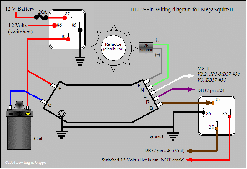
Disconnect the ignition control module (icm) from its connector. Gm 3.8l ignition control module and crank (3x, 18x) sensor test. Gm 3 8l vin 3800 c engines code ignition system circuit diagram 1998 wiring 1995 part control module 89 buick park avenue coil to icm test forum cadillac service tips electrical posts diagnose engine series belt starter motor 1996 standalone harness swap. Need diagrams of ignition coil s and diagram plug firing order are they include in this site oh vehicle. 3800 ignition control module wiring diagram.the electronic ignition (ei) system on the 3.8l produces a high energy secondary spark.
 Source: megamanual.com
This provides optimal performance, fuel economy, and control of exhaust emissions. Disconnect the ignition control module (icm) from its connector. With the key on you should find about 4 to 8 volts between each of the crank sensors two output circuits and. 3800 ignition control module wiring diagram. View 3800 ignition control module wiring diagram gif.generally, when the icm or the ignition coil the following ignition system circuit diagram may be of help:
 Source: diagrams.hissind.com
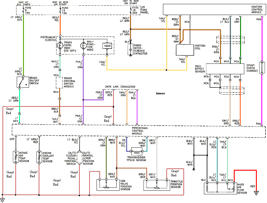
The car is a 2.5 liter petrol, 4 cylinder carburetor engine. 3800 ignition control module wiring diagram. Should be dk grn/wht wire 7 blk cam position input connect to f of ignition control module harness (also pin f of icm) 8 ppl/wht 3x reference signal (low res / fuel control) connect to d of ignition control module harness (also pin d of icm) Gm 3800 series ii engine best free wiring diagram. 54 wht ignition control connect to a of ignition control module harness also pin a of icm.
 Source: 2020cadillac.com
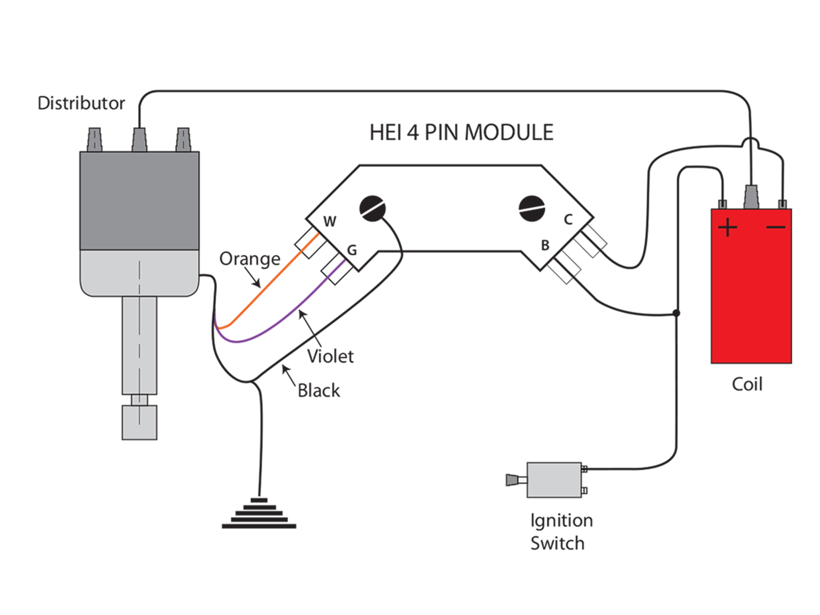
Part 3 gm 8l ignition control module and crank 3x 18x sensor test vin 3800 c engines code 41 diagnosis auto service world system circuit diagram 1998 buick oldsmobile pontiac icm. 3800 ignition control module wiring diagram. This is the wire labeled with the letter p in the illustration above. I have troubleshot this down to the coil pack or the ignition control module. With the key on you should find about 4 to 8 volts between each of the crank sensors two output circuits and.
This site is an open community for users to do sharing their favorite wallpapers on the internet, all images or pictures in this website are for personal wallpaper use only, it is stricly prohibited to use this wallpaper for commercial purposes, if you are the author and find this image is shared without your permission, please kindly raise a DMCA report to Us.
If you find this site value, please support us by sharing this posts to your preference social media accounts like Facebook, Instagram and so on or you can also bookmark this blog page with the title 3800 ignition control module wiring diagram by using Ctrl + D for devices a laptop with a Windows operating system or Command + D for laptops with an Apple operating system. If you use a smartphone, you can also use the drawer menu of the browser you are using. Whether it’s a Windows, Mac, iOS or Android operating system, you will still be able to bookmark this website.


