Your 3 wire rtd wiring diagram images are ready. 3 wire rtd wiring diagram are a topic that is being searched for and liked by netizens now. You can Download the 3 wire rtd wiring diagram files here. Get all royalty-free photos.
If you’re searching for 3 wire rtd wiring diagram pictures information linked to the 3 wire rtd wiring diagram topic, you have pay a visit to the right site. Our site always gives you hints for refferencing the highest quality video and image content, please kindly search and find more informative video articles and graphics that fit your interests.
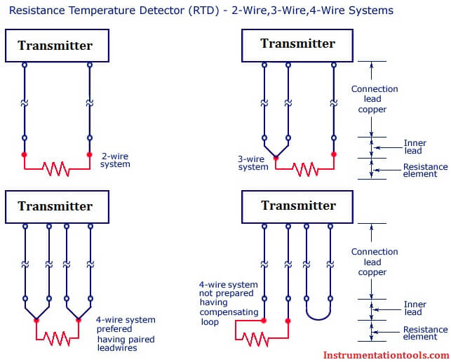
3 Wire Rtd Wiring Diagram. In this circuit there are three leads coming from the rtd instead of two. •noise and drift of the ref voltage are correlated and therefore canceled. 3 wire rtd wiring diagram in this circuit there are three leads coming from the rtd instead of two. In this circuit there are three leads coming from the rtd instead of two.
 3 wire rtd color code Colorpaints.co From colorpaints.co
2 wire rtd connections the 2 wire rtd configuration is the simplest among rtd circuit designs. A wiring diagram is a straightforward visual representation of the physical connections and physical layout of your electrical system or circuit. No current flows through it while the bridge is in balance.since l1 and l3 are in separate arms of the bridge,resistance is canceled. The reasoning for this is that the wires for the rtd are all pretty much the same gauge and length, so rather than having two pairs, the amplifier will just read one pair and use that resistance as the same for both wires. •idac generates the sensor excitation and the reference voltage. These leads can be connected to a special io card designed to accept rtd inputs or the leads can be connected to a temperature transmitter which will output a.
In this circuit there are three leads coming from the rtd instead of two.
(to din 47100) white, brown, green, yellow, grey, pink color coding: The 3 wire rtds use a third wire to measure and compensate for some of the effects of the resistance of the lead wires on the temperature measurement especially in cases where the temperature sensor is located far from the temperature transmitter. •noise and drift of the ref voltage are correlated and therefore canceled. There is a lead resistance in each arm of the bridge so that the resistance is cancelled out, so long as the two lead resistances are accurately the same. 3 wire rtd wiring diagram. Measuring temperature from pt100 using arduino arduino arduino projects sensors technology.
 Source: lightswitchplatform.blogspot.com
Rtd pt100 3 wire wiring diagram sor resistance temperature detector rtd proflow systems. Lead wire configuration, lead wires can be attached in 2, 3 or 4 wire configurations for both simplex and duplex elements. L1 and l3 carry the measuring current while l2 acts only as a potential lead. •allows complete utilization of the input range, no offset caused by the rtd itself. Difference between 2 wire rtd 3 wire rtd and 4 wire rtds rtds resistance temperature detectors are offered with 2 3 or 4 lead configuration.

L1 and l3 carry the measuring current while l2 acts only as a potential lead. L1 and l3 carry the measuring current while l2 acts only as a potential lead. These leads can be connected to a special io card designed to accept rtd inputs or the leads can be connected to a temperature transmitter which will output a. Rtd pt100 3 wire wiring diagram sor resistance temperature detector rtd proflow systems. No current flows through it while the bridge is in balance.
 Source: wholefoodsonabudget.com
There is a lead resistance in each arm of the bridge so that the resistance is cancelled out, so long as the two lead resistances are accurately the same. R1 l1 rt r2 r3 l2 l1 es eo r1 rt r2 r3 l2 es l1 rt rt rt l4 l3 l2 is eo wiring diagrams Electronic wiring majorcom electrical diagram arduino sensors diagram. 100 ohm platinum rtd sensor chart wheatstone bridge sensor ohms. The 3 wire rtds use a third wire to measure and compensate for some of the effects of the resistance of the lead wires on the temperature measurement especially in cases where the temperature sensor is located far from the temperature transmitter.
 Source: tekonelectronics.com
3 wire rtd wiring diagram november 24, 2021. Electronic wiring majorcom electrical diagram arduino sensors diagram. It shows how a electrical wires are interconnected which enable it to also show where fixtures and components may be coupled to the system. In this circuit there are three leads coming from the rtd instead of two. •idac generates the sensor excitation and the reference voltage.
 Source: wiringall.com
L1 and l3 carry the measuring current while l2 acts only as a potential lead. It shows the components of the circuit as simplified shapes and the faculty and signal friends amid the devices. The reasoning for this is that the wires for the rtd are all pretty much the same gauge and length, so rather than having two pairs, the amplifier will just read one pair and use that resistance as the same for both wires. L1 and l3 carry the measuring current while l2 acts only as a potential lead. Using this method the two leads to the sensor are on adjoining arms.
 Source: wholefoodsonabudget.com
It is showing the possibility for connection of 4no.s of rtd instead of 8no.s. Lead wire configuration, lead wires can be attached in 2, 3 or 4 wire configurations for both simplex and duplex elements. •idac generates the sensor excitation and the reference voltage. The reasoning for this is that the wires for the rtd are all pretty much the same gauge and length, so rather than having two pairs, the amplifier will just read one pair and use that resistance as the same for both wires. Rtd wiring configurations there are three types of wire configurations, 2 wire, 3 wire, and 4 wire, that are commonly used in rtd sensing circuits.
 Source: colorpaints.co
R1 l1 rt r2 r3 l2 l1 es eo r1 rt r2 r3 l2 es l1 rt rt rt l4 l3 l2 is eo wiring diagrams It shows the components of the circuit as simplified shapes and the faculty and signal friends amid the devices. Difference between 2 wire rtd 3 wire rtd and 4 wire rtds rtds resistance temperature detectors are offered with 2 3 or 4 lead configuration. L1 and l3 carry the measuring current while l2 acts only as a potential lead. Literally a circuit is the path that permits electricity to circulation.
 Source: puertoricoinform.blogspot.com
L1 and l3 carry the measuring current while l2 acts only as a potential lead. Because a very small change in resistance happens with each degree in temperature the. It shows the components of the circuit as simplified shapes and the faculty and signal friends amid the devices. Literally a circuit is the path that permits electricity to circulation. A wiring diagram is a straightforward visual representation of the physical connections and physical layout of your electrical system or circuit.
 Source: wiring89.blogspot.com
No current flows through it while the bridge is in balance. Electronic wiring majorcom electrical diagram arduino sensors diagram. L1 and l3 carry the measuring current while l2 acts only as a potential lead. Most rtd’s incorporate a third wire with resistance r3. In this circuit there are three leads coming from the rtd instead of two.
 Source: wiring121.blogspot.com
L1 and l3 carry the measuring current while l2 acts only as a potential lead. Thermocouple wire is not required to connect an rtd. L1 and l3 carry the measuring current while l2 acts only as a potential lead. 3 wire rtd wiring diagram. •allows complete utilization of the input range, no offset caused by the rtd itself.
 Source: worldvisionsummerfest.com
3 wire rtd wiring diagram. Diagram pt100 3 wire rtd wiring diagram full version hd quality wiring diagram wiring4youn previtech it from tse3.mm.bing.net i added the pt100 board to my duetwifi i have a two wire thermocouple. R1 l1 rt r2 r3 l2 l1 es eo r1 rt r2 r3 l2 es l1 rt rt rt l4 l3 l2 is eo wiring diagrams •voltage drop across the line resistance are compensated. (to din 47100) white, brown, green, yellow, grey, pink color coding:
![[MK_9839] Three Wire Rtd Wiring Diagram For Schematic Wiring [MK_9839] Three Wire Rtd Wiring Diagram For Schematic Wiring](https://static-cdn.imageservice.cloud/4127669/rtd-pt100-3-wire-wiring-diagram-gallery-wiring-diagram-sample.jpg) Source: atolo.unbe.perm.itis.mohammedshrine.org
Source: atolo.unbe.perm.itis.mohammedshrine.org
Electronic wiring majorcom electrical diagram arduino sensors diagram. L1 and l3 carry the measuring current while l2 acts only as a potential lead. R1 l1 rt r2 r3 l2 l1 es eo r1 rt r2 r3 l2 es l1 rt rt rt l4 l3 l2 is eo wiring diagrams It shows the components of the circuit as simplified shapes and the faculty and signal friends amid the devices. In this circuit there are three leads coming from the rtd instead of two.
 Source: schematron.org
No current flows through it while the bridge is in balance.since l1 and l3 are in separate arms of the bridge,resistance is canceled. 3 wire rtd wiring diagram in this circuit there are three leads coming from the rtd instead of two. Lead wire configuration, lead wires can be attached in 2, 3 or 4 wire configurations for both simplex and duplex elements. 2 wire rtd connections the 2 wire rtd configuration is the simplest among rtd circuit designs. Measuring temperature from pt100 using arduino arduino arduino projects sensors technology.

There is a lead resistance in each arm of the bridge so that the resistance is cancelled out, so long as the two lead resistances are accurately the same. A wiring diagram is a straightforward visual representation of the physical connections and physical layout of your electrical system or circuit. Literally a circuit is the path that permits electricity to circulation. This wire will be connected to one side of the resistance element along with lead 2. 3 wire rtd wiring diagram in this circuit there are three leads coming from the rtd instead of two.

A wiring diagram is a straightforward visual representation of the physical connections and physical layout of your electrical system or circuit. 3 wire rtd wiring diagram. L1 and l3 carry the measuring current while l2 acts only as a potential lead. In this circuit there are three leads coming from the rtd instead of two. •idac generates the sensor excitation and the reference voltage.
 Source: wiringall.com
Literally a circuit is the path that permits electricity to circulation. Using this method the two leads to the sensor are on adjoining arms. The 3 wire rtds use a third wire to measure and compensate for some of the effects of the resistance of the lead wires on the temperature measurement especially in cases where the temperature sensor is located far from the temperature transmitter. 3 wire rtd wiring diagram. L1 and l3 carry the measuring current while l2 acts only as a potential lead.
 Source: wholefoodsonabudget.com
Lead wire configuration, lead wires can be attached in 2, 3 or 4 wire configurations for both simplex and duplex elements. 3 wire rtd wiring diagram november 24, 2021. It shows the components of the circuit as simplified shapes and the faculty and signal friends amid the devices. Thermocouple wire is not required to connect an rtd. No current flows through it while the bridge is in balance.
 Source: worldvisionsummerfest.com
L1 and l3 carry the measuring current while l2 acts only as a potential lead. •voltage drop across the line resistance are compensated. 3 wiring diagram for thermocouples. Thermocouple wire is not required to connect an rtd. Most rtd’s incorporate a third wire with resistance r3.
This site is an open community for users to share their favorite wallpapers on the internet, all images or pictures in this website are for personal wallpaper use only, it is stricly prohibited to use this wallpaper for commercial purposes, if you are the author and find this image is shared without your permission, please kindly raise a DMCA report to Us.
If you find this site good, please support us by sharing this posts to your own social media accounts like Facebook, Instagram and so on or you can also bookmark this blog page with the title 3 wire rtd wiring diagram by using Ctrl + D for devices a laptop with a Windows operating system or Command + D for laptops with an Apple operating system. If you use a smartphone, you can also use the drawer menu of the browser you are using. Whether it’s a Windows, Mac, iOS or Android operating system, you will still be able to bookmark this website.


