Your 3 wire maf sensor wiring diagram images are ready. 3 wire maf sensor wiring diagram are a topic that is being searched for and liked by netizens today. You can Find and Download the 3 wire maf sensor wiring diagram files here. Find and Download all royalty-free vectors.
If you’re looking for 3 wire maf sensor wiring diagram images information linked to the 3 wire maf sensor wiring diagram interest, you have pay a visit to the ideal site. Our site frequently provides you with suggestions for refferencing the highest quality video and picture content, please kindly hunt and find more informative video content and images that fit your interests.
3 Wire Maf Sensor Wiring Diagram. It is supposed to aid all of the average person in building a correct program. 1 trick that we 2 to printing a similar wiring plan off twice. With this sort of an illustrative guidebook, you will be able to troubleshoot, prevent, and complete your assignments easily. Wiring diagram comes with a number of easy to follow wiring diagram directions.
 Bmw E46 Maf Wiring Diagram From wiringdiagramall.blogspot.com
Ecoboost maf sensor from www.picoauto.com i know that the iat (intake air temperature sensor) is integrated into to maf sensor but which wires belong to. On the other hand, this diagram is a simplified version of this arrangement. 3 wire to 5 wire maf wiring diagram? With such an illustrative guidebook, you are going to be able to troubleshoot, avoid, and total your tasks with ease. A vehicle wiring diagram is a lot like a road map, according to search auto. I also show you how you can figure out the wires without a wiring diagram.
Otherwise, the structure won’t function as it ought to be.
The sensor, commonly called the maf sensor, tells the engine�s computer how much air is going into the engine. 3, 4, & 5 wire mass air flow sensor wiring diagram mass air flow sensor wiring diagram. 1 trick that we 2 to printing a similar wiring plan off twice. 3 wire to 5 wire maf wiring diagram? Each component should be placed and linked to different parts in particular manner. Each component should be placed and linked to different parts in particular manner.
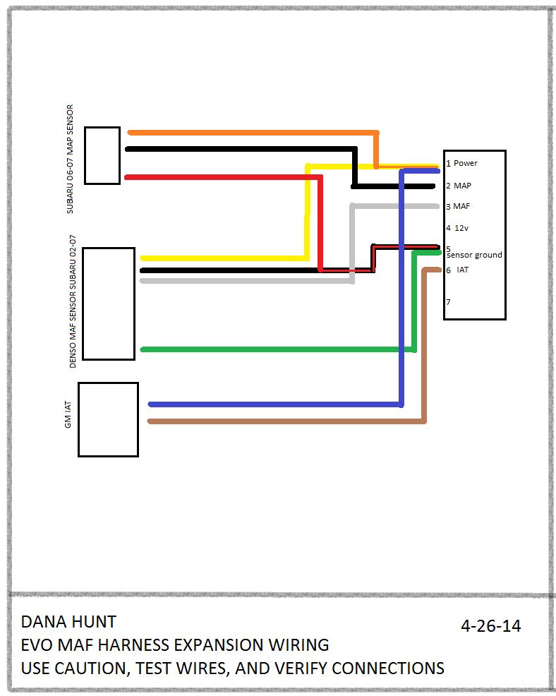 Source: wiringschemas.blogspot.com
With this sort of an illustrative guidebook, you will be able to troubleshoot, prevent, and complete your assignments easily. But, it does not imply link between the wires. Acceptthe most common way to test the 5 wire vw mass air flow maf sensor is just to unplug it with the engine running. Wiring 3 wire dc sensors can be confusing. Occasionally, the cables will cross.
 Source: justanswer.com
If the engine stalls occasionally, start the engine and shake the maf sensor harness. It is supposed to aid all of the average person in building a correct program. As stated previous, the traces at a maf wiring diagram signifies wires. I also show you how you can figure out the wires without a wiring diagram. Not only will it help you achieve your required results more quickly, but additionally make the whole procedure easier for everybody.
 Source: diagramweb.net
Otherwise, the structure won’t function as it ought to be. 3 wire maf sensor wiring diagram. Will only know then when i try to wire in the maf as the wirjng is not part of the engine wiring harness going to injectors, turbo etc. If the wires are okay, replace mass air flow (maf) sensor. These directions will probably be easy to grasp and implement.
 Source: wiringdiagrammechanic.blogspot.com
If the engine stalls, check for poor contact at the maf sensor connector. Ecoboost maf sensor from www.picoauto.com i know that the iat (intake air temperature sensor) is integrated into to maf sensor but which wires belong to. Each component should be placed and linked to different parts in particular manner. I also show you how you can figure out the wires without a wiring diagram. A vehicle wiring diagram is a lot like a road map, according to search auto.

Here is a video on how you can test your maf sensor using a basic $5 multimeter. If the engine stalls occasionally, start the engine and shake the maf sensor harness. Maf sensor wiring diagram 1997 1999 for 5 wire schematic ford truck 3 4 mass air flow 1 8 help miata 2003 mustang gt 1996 how to test a my pro street wilbo666 toyota sensors. I also show you how you can figure out the wires without a wiring diagram. This makes the procedure for assembling circuit simpler.
 Source: diagramweb.net
Wiring 3 wire dc sensors can be confusing. With this sort of an illustrative guidebook, you will be able to troubleshoot, prevent, and complete your assignments easily. On the other hand, this diagram is a simplified version of this arrangement. 1 trick that we 2 to printing a similar wiring plan off twice. Each component should be placed and linked to different parts in particular manner.
 Source: justanswer.com
Injunction of two wires is usually indicated by black dot at the junction of 2 lines. Maf sensor wiring diagram 1997 1999 ford 4 6l 5 4l index of articles. Each part ought to be placed and connected with different parts in particular way. 3 wire to 5 wire maf wiring diagram? On the other hand, this diagram is a simplified version of this arrangement.
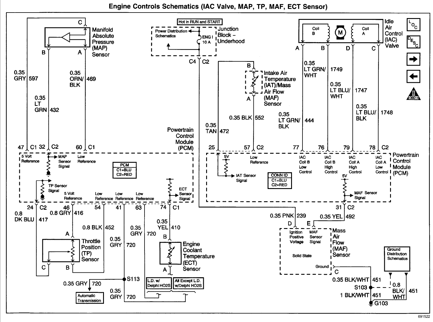 Source: ls1tech.com
A sensor out of calibration may rise too quickly in reaction to the rpm. 1 trick that we 2 to printing a similar wiring plan off twice. Each component should be placed and linked to different parts in particular manner. Will only know then when i try to wire in the maf as the wirjng is not part of the engine wiring harness going to injectors, turbo etc. 3, 4, & 5 wire mass air flow sensor wiring diagram mass air flow sensor wiring diagram.
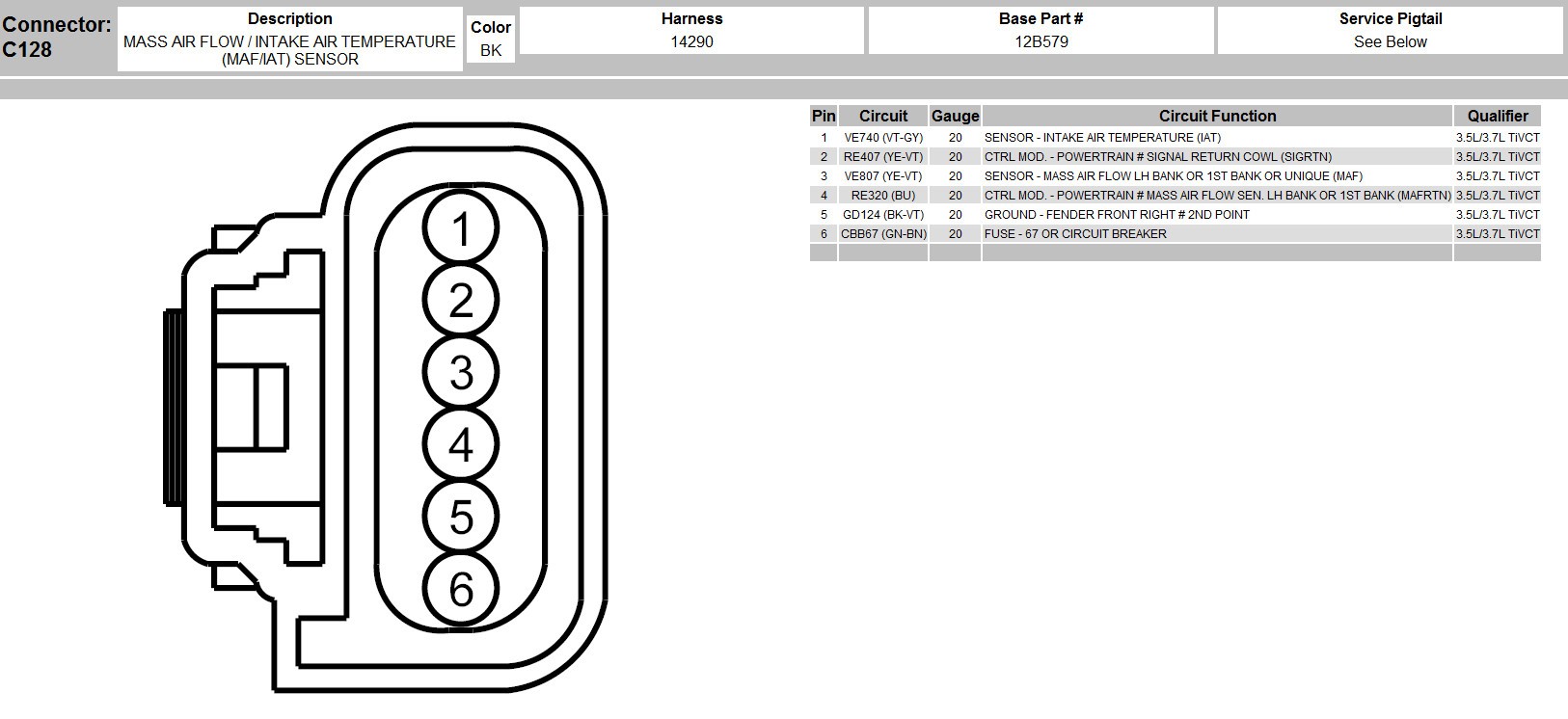 Source: mainetreasurechest.com
If the wires are okay, replace mass air flow (maf) sensor. If the wires are okay, replace mass air flow (maf) sensor. Each component should be placed and linked to different parts in particular manner. 3 wire maf sensor wiring diagram. With this sort of an illustrative guidebook, you will be able to troubleshoot, prevent, and complete your assignments easily.
 Source: easyautodiagnostics.com
Occasionally, the cables will cross. Avalanche, sierra, silverado, c&k series, pin, wire color, circuit no. Maf sensor wiring diagram 1997 1999 ford 4 6l 5 4l index of articles. With this sort of an illustrative guidebook, you will be able to troubleshoot, prevent, and complete your assignments easily. In the latest model car, the iat sensor is built into the map and maf sensor.
 Source: wiringdiagramall.blogspot.com
On the other hand, this diagram is a simplified version of this arrangement. 3 wire to 5 wire maf wiring diagram? Maf sensor connector pinout on l, l, l engines. It is supposed to aid all of the average person in building a correct program. Maf sensor wiring diagram 1997 1999 ford 4 6l 5 4l index of articles.

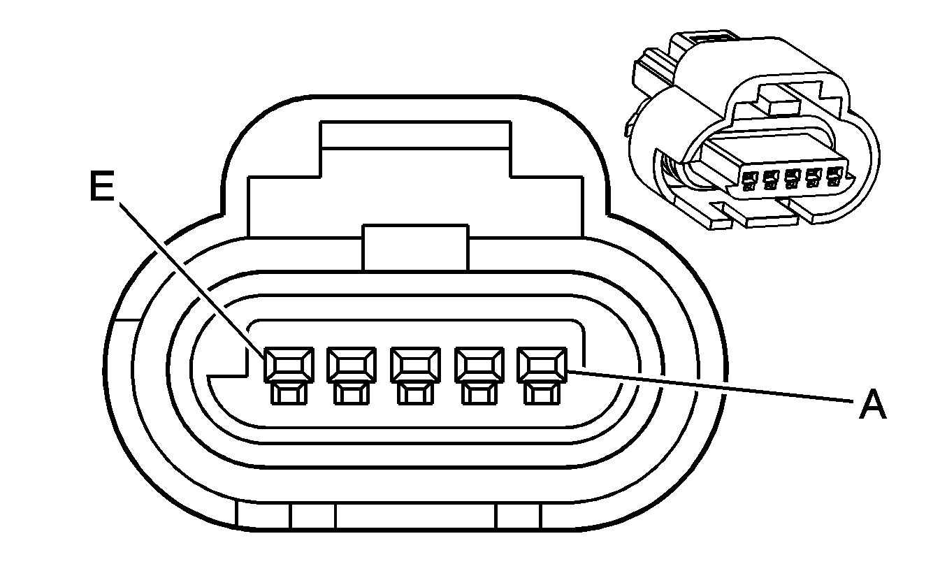
Gm maf sensor wiring diagram wiring diagram is a simplified welcome pictorial representation of an electrical circuit. These directions will probably be easy to grasp and implement. On the other hand, this diagram is a simplified version of this arrangement. Maf sensor connector pinout on l, l, l engines. Acceptthe most common way to test the 5 wire vw mass air flow maf sensor is just to unplug it with the engine running.
 Source: justanswer.com
If the engine stalls, check for poor contact at the maf sensor connector. Maf sensor wiring diagram 1997 1999 ford 4 6l 5 4l index of articles. Your vehicle could start to act like it has a bad coil pack or throttle position sensor and after testing those you may still come up empty handed. 3 wire mass air flow sensor wiring diagram. If the engine stalls, check for poor contact at the maf sensor connector.

3 wire maf sensor wiring diagram. 3 wire to 5 wire maf wiring diagram? 3 wire maf sensor wiring diagram. It shows the components of the circuit as simplified shapes and the capability and signal contacts in the company of the devices. With this sort of an illustrative guidebook, you will be able to troubleshoot, prevent, and complete your assignments easily.
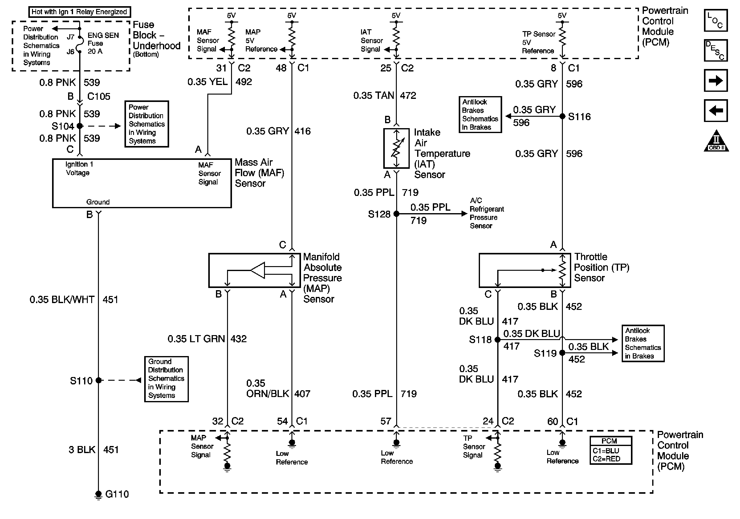 Source: ls1tech.com
3 wire maf sensor wiring diagram. 3 wire mass air flow sensor wiring diagram. Maf sensor wiring diagram 1997 1999 for 5 wire schematic ford truck 3 4 mass air flow 1 8 help miata 2003 mustang gt 1996 how to test a my pro street wilbo666 toyota sensors. Will only know then when i try to wire in the maf as the wirjng is not part of the engine wiring harness going to injectors, turbo etc. Blx doesnt have maf only temp sensor on airbox so this is why this thread started.
![[DIAGRAM] Mass Air Flow Sensor Wiring Diagram 2009 Ford [DIAGRAM] Mass Air Flow Sensor Wiring Diagram 2009 Ford](http://ww2.justanswer.com/uploads/xsvectOR/2010-11-13_030647_1.gif) Source: diagramrefd.spaghettiswing.it
Source: diagramrefd.spaghettiswing.it
Injunction of two wires is usually indicated by black dot at the junction of 2 lines. There’ll be principal lines that are represented by l1, l2, l3, and so on. It shows the components of the circuit as simplified shapes and the capability and signal contacts in the company of the devices. With this sort of an illustrative guidebook, you will be capable of troubleshoot, avoid, and complete your tasks easily. Your vehicle could start to act like it has a bad coil pack or throttle position sensor and after testing those you may still come up empty handed.
 Source: wiringschemas.blogspot.com
Will only know then when i try to wire in the maf as the wirjng is not part of the engine wiring harness going to injectors, turbo etc. Each part should be set and linked to other parts in particular manner. This makes the procedure for assembling circuit simpler. With this sort of an illustrative guidebook, you will be able to troubleshoot, prevent, and complete your assignments easily. 3 wire maf sensor wiring diagram.
 Source: wiringschemas.blogspot.com
These directions will probably be easy to grasp and implement. A vehicle wiring diagram is a lot like a road map, according to search auto. If the engine stalls, check for poor contact at the maf sensor connector. Blx doesnt have maf only temp sensor on airbox so this is why this thread started. Wiring diagram comes with a number of easy to follow wiring diagram directions.
This site is an open community for users to do submittion their favorite wallpapers on the internet, all images or pictures in this website are for personal wallpaper use only, it is stricly prohibited to use this wallpaper for commercial purposes, if you are the author and find this image is shared without your permission, please kindly raise a DMCA report to Us.
If you find this site convienient, please support us by sharing this posts to your own social media accounts like Facebook, Instagram and so on or you can also save this blog page with the title 3 wire maf sensor wiring diagram by using Ctrl + D for devices a laptop with a Windows operating system or Command + D for laptops with an Apple operating system. If you use a smartphone, you can also use the drawer menu of the browser you are using. Whether it’s a Windows, Mac, iOS or Android operating system, you will still be able to bookmark this website.

