Your 3 phase water pump control panel wiring diagram images are ready in this website. 3 phase water pump control panel wiring diagram are a topic that is being searched for and liked by netizens today. You can Download the 3 phase water pump control panel wiring diagram files here. Find and Download all free images.
If you’re searching for 3 phase water pump control panel wiring diagram images information related to the 3 phase water pump control panel wiring diagram interest, you have visit the right site. Our website always provides you with hints for viewing the highest quality video and picture content, please kindly search and find more informative video content and images that match your interests.
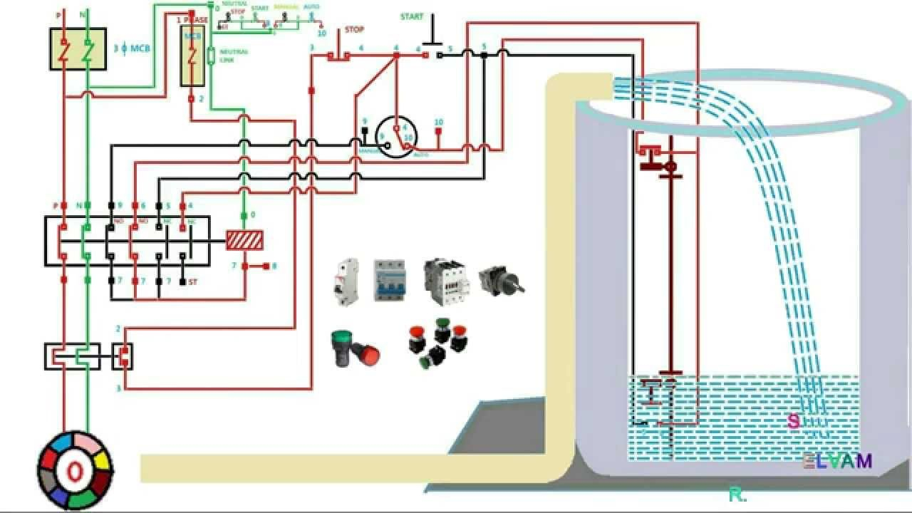
3 Phase Water Pump Control Panel Wiring Diagram. 8 9 2018 wiring diagram images detail herald single phase submersible pump starter wiring diagram submersible pump control panel circuit diagram best awesome single phase water pump control panel wiring file type jpg source kmestc com size 187 49 kb dimension 570 x 600. Automatic water level controller wiring diagram for 3 phase motor submersible pump in 2020 water pump motor submersible pump electrical installation. Collection of submersible pump control box wiring diagram. Water pump wiring troubleshooting repair diagrams aim manual page 54 single phase motors and controls motor maintenance north america franklin electric electrician submersible starter facebook jet controller circuit homemade projects madhav control panel mini.
 Submersible Motor Control Box Wiring Single Phase water From youtube.com
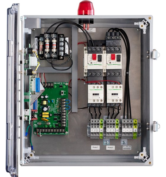
Pumps and control circuit or the control circuit can be wired to a separate power supply to insure alarm integrity in case of a tripped main breaker. Water pump motor automatic and manual control | float switch wiring diagram | 3 phase. Both setups use two 12 volt 60 or. • color coded wiring, screw type terminals and plug in sockets, ensure ease of field servicing. Submersible pump control box wiring diagram for 3 wire single. 8 9 2018 wiring diagram images detail herald single phase submersible pump starter wiring diagram submersible pump control panel circuit diagram best awesome single phase water pump control panel wiring file type jpg source kmestc com size 187 49 kb dimension 570 x 600.
3 phase submersible pump control panel circuit diagram.
• color coded wiring, screw type terminals and plug in sockets, ensure ease of field servicing. A wiring diagram is a streamlined traditional photographic representation of an electrical circuit. 3 phase submersible pump control panel circuit diagram. A wiring diagram is a streamlined standard pictorial depiction of an electric circuit. Stock photo 3 phase wiring diagram for house 3 phase wiring installation in house 3 phase d electrical wiring electrical circuit diagram home electrical wiring. 3 phase water pump control panel wiring diagram wiring view and schematics diagram this area is a growing library of the schematics, wiring diagrams and technical photos
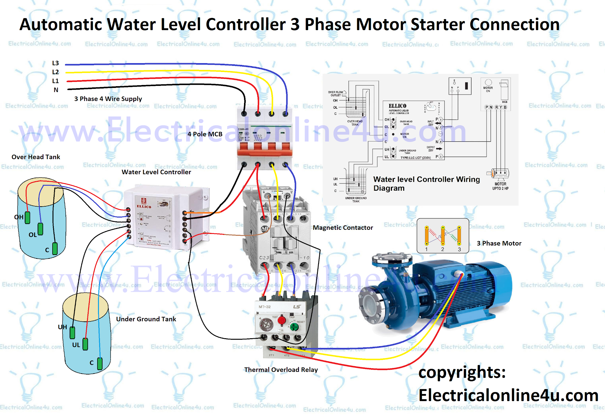 Source: electricalonline4u.com
3 phase submersible pump wiring diagram. It shows the elements of the circuit as simplified forms and also the power as well as signal links between the devices. • color coded wiring, screw type terminals and plug in sockets, ensure ease of field servicing. It has inbuilt single phase. Single action, vertical and wide angle.
 Source: diary-of-electric.blogspot.com
3 phase to single phase wiring diagram in 2021 electrical wiring diagram diagram circuit diagram single phase motor water pump control magnetic contactor with indicator youtube water pumps pumps water Now look to see if the breaker takes up two breaker spaces or one. Check more diagrams like this here: Single action control switches can only be connected through a control panel. 8 9 2018 wiring diagram images detail herald single phase submersible pump starter wiring diagram submersible pump control panel circuit diagram best awesome single phase water pump control panel wiring file type jpg source kmestc com size 187 49 kb dimension 570 x 600.
 Source: favpng.com
Here i showed the forward reverse wiring diagram. 240 volt well pump wiring diagram wiring diagram is a simplified all right pictorial representation of an electrical circuit it shows the components of the circuit. Power circuit of star delta starter electrical info pics power engineering. 3 phase submersible pump wiring diagram. It has inbuilt single phase.
 Source: youtube.com
Wiring diagram of a single phase water pump wiring diagram line wiring diagram. Here i showed the forward reverse wiring diagram. Check more diagrams like this here: A wiring diagram is a streamlined standard pictorial depiction of an electric circuit. • auxiliary alarm contacts provided for remote alarm connection.
 Source: pinterest.com
Single action, vertical and wide angle. New car wiring diagram explained diagram diagramtemplate diagramsample electrical circuit diagram electri. 3 phase submersible pump wiring diagram. 3 phase water pump control panel wiring diagram wiring view and schematics diagram this area is a growing library of the schematics, wiring diagrams and technical photos Submersible pump control box wiring diagram for 3 wire single phase submersible pump submersible well pump submersible.
 Source: pinterest.com
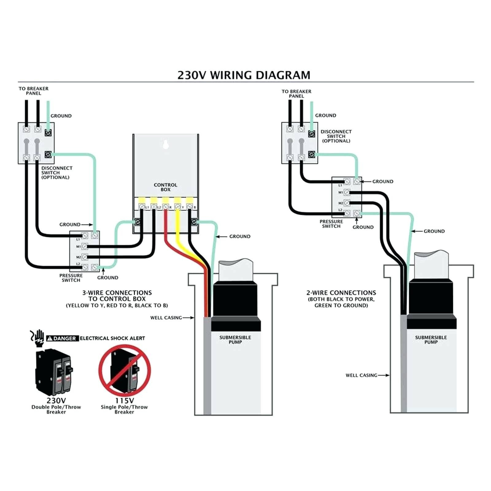
Wiring diagram of a single phase water pump wiring diagram line wiring diagram. A wiring diagram is a streamlined standard pictorial depiction of an electric circuit. Wiring diagram of a single phase water pump wiring diagram line wiring diagram. It has inbuilt single phase. Phase 230v wiring diagram three phase 460v wiring diagram three phase 575v wiring diagram kb pump wiring diagrams kb pump 230v wiring, single phase water pump control panel wiring diagram fresh 3 wire submersible tech topics simplify water well pump control circuits setup rh nationaldriller 3 phase generator wiring heater control wiring
 Source: annawiringdiagram.com
3 phase to single phase wiring diagram in 2021 electrical wiring diagram diagram circuit diagram single phase motor water pump control magnetic contactor with indicator youtube water pumps pumps water It shows the elements of the circuit as simplified forms and also the power as well as signal links between the devices. Start at the breaker panel. Automatic water level controller wiring diagram for 3 phase motor submersible pump water pump motor submersible pump electrical installation. R , y, b = red, yellow, blue ( 3 phase lines)c.b = general circuit breakermain = mai supplyy = starδ = deltac1, c2, c3 = contatcors (power diagram)o/l = over load relayno = normally opennc = normally closed k1 = contactor (contactor coil) k1/no = contactor holding coil (normally open)k1 , k2, k3 = contators (for.
 Source: researchgate.net
Swimming pool electrical wiring diagram in 2021 pool filters pool electrical swimming pool. For the water to enter your house however you should also have your own pump. 3 phase to single phase wiring diagram in 2021 electrical wiring diagram diagram circuit diagram single phase motor water pump control magnetic contactor with indicator youtube water pumps pumps water 2 wire well pump diagrams are slightly easier to understand and are more straight forward to wire. Water pump wiring troubleshooting repair diagrams aim manual page 54 single phase motors and controls motor maintenance north america franklin electric electrician submersible starter facebook jet controller circuit homemade projects madhav control panel mini.
 Source: ricardolevinsmorales.com
3 phase water pump wiring diagram buy 2 2kw 220v frequency inverter 3 phase output ac motor water pump controller ict at affordable prices free. 3 phase submersible pump wiring diagram. Check more diagrams like this here: Correct wiring for 3 wire single phase. A wiring diagram is a streamlined traditional photographic representation of an electrical circuit.
 Source: annawiringdiagram.com
Collection of submersible pump control box wiring diagram. 44 luxury single phase submersible pump starter wiring diagram submersible well pump jet pump well pump. Water pump motor automatic and manual control | float switch wiring diagram | 3 phase. Pumps and control circuit or the control circuit can be wired to a separate power supply to insure alarm integrity in case of a tripped main breaker. Sump pump control wiring diagram another photograph.
 Source: pinterest.com
Water pump controller with float switchauto manual connection of water pump. Single action, vertical and wide angle. Float switch wiring diagram for water pump youtube solar powered water pump. For the water to enter your house however you should also have your own pump. Three phase motor & control installation wiring diagrams.
 Source: youtube.com
It shows the elements of the circuit as simplified forms and also the power as well as signal links between the devices. A three wire control circuit uses momentary contact, start/stop stations, and a normally open seal in contact connected in parallel with the start button to maintain. New car wiring diagram explained diagram diagramtemplate diagramsample electrical circuit diagram electri. 3 phase submersible pump control panel circuit diagram. Float switch wiring diagram for water pump youtube solar powered water pump.
 Source: seewaterinc.com
3 phase submersible pump starter wiring diagram. For the water to enter your house however you should also have your own pump. Automatic water level controller wiring diagram for 3 phase motor submersible pump submersible pump water pump motor electrical installation. Three wire pumps need an extra control panel above ground. Collection of submersible pump control box wiring diagram.
 Source: youtube.com
Water pump controller with float switchauto manual connection of water pump motor w. Both setups use two 12 volt 60 or. Water pump controller with float switchauto manual connection of water pump. Submersible water pump wiring diagram. Float switch wiring diagram for water pump youtube solar powered water pump.
 Source: youtube.com
3 phase water pump control panel wiring diagram wiring view and schematics diagram this area is a growing library of the schematics, wiring diagrams and technical photos A three wire control circuit uses momentary contact, start/stop stations, and a normally open seal in contact connected in parallel with the start button to maintain. For the water to enter your house however you should also have your own pump. Automatic water level controller wiring diagram for 3 phase motor submersible pump in 2020 water pump motor submersible pump electrical installation. 2 wire well pump diagrams are slightly easier to understand and are more straight forward to wire.
 Source: dentistmitcham.com
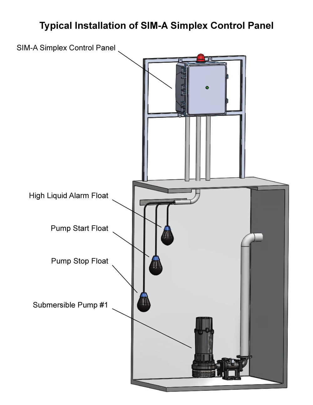
Wiring from the sump to the control panel shall have separate conduits for the pump power and for. Single action, vertical and wide angle. Pumps and control circuit or the control circuit can be wired to a separate power supply to insure alarm integrity in case of a tripped main breaker. Start at the breaker panel. 2 wire well pump diagrams are slightly easier to understand and are more straight forward to wire.
 Source: seewaterinc.com
8 9 2018 wiring diagram images detail herald single phase submersible pump starter wiring diagram submersible pump control panel circuit diagram best awesome single phase water pump control panel wiring file type jpg source kmestc com size 187 49 kb dimension 570 x 600. 2 wire well pump diagrams are slightly easier to understand and are more straight forward to wire. Here i showed the forward reverse wiring diagram. Both setups use two 12 volt 60 or. Wiring diagram of a single phase water pump wiring diagram line wiring diagram.
 Source: perantausepilodge.blogspot.com
Automatic water level controller wiring diagram for 3 phase motor submersible pump submersible pump water pump motor electrical installation. The auto unit in bch submersible panel primarily detects the presence or absence of all three phase. Automatic water level controller wiring diagram for 3 phase motor submersible pump submersible pump water pump motor electrical installation wiring diagram for 220 volt submersible pump submersible pump 1993 ford mustang wiring diagram 2001 ford mus submersible pump submersible well pump sump pump 3 phase water pump wiring diagram buy 2 2kw 220v frequency inverter 3 phase output ac motor water pump controller ict at affordable prices free. Both setups use two 12 volt 60 or.
This site is an open community for users to share their favorite wallpapers on the internet, all images or pictures in this website are for personal wallpaper use only, it is stricly prohibited to use this wallpaper for commercial purposes, if you are the author and find this image is shared without your permission, please kindly raise a DMCA report to Us.
If you find this site value, please support us by sharing this posts to your favorite social media accounts like Facebook, Instagram and so on or you can also bookmark this blog page with the title 3 phase water pump control panel wiring diagram by using Ctrl + D for devices a laptop with a Windows operating system or Command + D for laptops with an Apple operating system. If you use a smartphone, you can also use the drawer menu of the browser you are using. Whether it’s a Windows, Mac, iOS or Android operating system, you will still be able to bookmark this website.

