Your 3 phase rcd wiring diagram images are ready. 3 phase rcd wiring diagram are a topic that is being searched for and liked by netizens now. You can Download the 3 phase rcd wiring diagram files here. Get all free images.
If you’re looking for 3 phase rcd wiring diagram images information connected with to the 3 phase rcd wiring diagram keyword, you have come to the ideal blog. Our website always provides you with hints for seeing the maximum quality video and image content, please kindly search and find more informative video articles and graphics that fit your interests.
3 Phase Rcd Wiring Diagram. 3 phase house wiring diagram pdf. It reveals the elements of the circuit as streamlined forms and the power and signal connections between the tools. Just like below image diagram connect the in voltage l1 l2 l3 and neutral to in terminals of breaker and then connect same the out. This post is about the 3 phase kwh meter wiring diagram.

Wiring a four poles rcbo or gfci circuit breaker (three phase rccb wiring) the three phase wiring for gfci or rcd (rccb) or rcbo wiring diagram shows the three lines (l1, l2 and l3) and neutral has been connected as input to. Clipsal rc and 4rc series residual current device wiring diagrams 1 2 main switch single phase e 3n 4n clipsal rcbm 4rcbm and 4rcbe series combined mcbrcd wiring diagram a warning combined max. Schematic wiring diagram of three phase distribution board. 3 phase house wiring diagram pdf. Just like below image diagram connect the in voltage l1 l2 l3 and neutral to in terminals of breaker and then connect same the out. How to wire an abb rcd with no neutral line.
3 phase distribution board wiring diagram pdf wiring diagram is a simplified tolerable pictorial representation of an electrical circuit it shows the components of the circuit as simplified shapes and the aptitude and signal contacts amongst the devices.
Should it be necessary to use a 4 pole rcd for a single phase circuit, poles 3 / 4 and n must be used, with a link between poles 5 / 6 and n (1.5mm² wire), otherwise the test device will not be energised when the test button is pressed and will not function. 3 phase distribution board wiring basic electrical design of a plc panel diy consumer unit and to wire db hvac control diagram full what is single three. 6 when using a 4 pole rcd on a three phase 3 wire system, the n pole should not be used. 3 phase panel board wiring diagram pdf. What is single phase and three electric systems sescos 3 wiring for dummies understanding motor connections hut wire 240 to voltage rs 5550 piece aggarwal electricals id 13431273530 how make a with wires work quora android sample distribution system scientific diagram apply power supply fabricante de fuentes alimentación conmutadas mean well fuente. In the case of a rcd with a phase to phase test circuit, there are no special requirements and the test function will operate with a three wire connection.
 Source: pinterest.com.au
3 phase panel board wiring diagram pdf. Just like below image diagram connect the in voltage l1 l2 l3 and neutral to in terminals of breaker and then connect same the out. In the 3 phase wiring system, the single phase and three phase can be connect as shown as below figure. It reveals the elements of the circuit as streamlined forms and the power and signal connections between the tools. 4 wire three phase wye wiring system inst tools.
 Source: pinterest.com
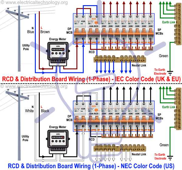
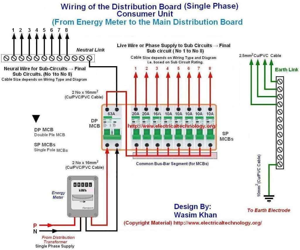
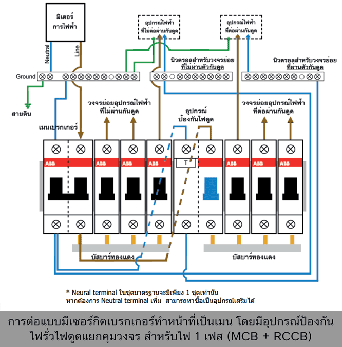
Thinking about electrical needs for a tiny house. Need to wire three 230v a 4 pole 240v 30a plug phase. Three phase electrical wiring installation in a multi story building electrical wiring electrical panel wiring house wiring Wiring diagram a 3 phase isolator with a stop button. In the above distribution diagram i have shown the wiring installation of double pole mcb circuit breaker rcd circuit breaker single pole mcb breakers voltmeter light indicator.

Wiring diagram according to old colour code. This post is about the 3 phase kwh meter wiring diagram. 3 phase rcd wiring diagram australia. 4 wire three phase wye wiring system inst tools. Clipsal rc and 4rc series residual current device wiring diagrams 1 2 main switch single phase e 3n 4n clipsal rcbm 4rcbm and 4rcbe series combined mcbrcd wiring diagram a warning combined max.
 Source: electricaltechnology.org
Three phases of a supply voltage of 380 volts and a neutral working conductor are connected to the four input terminals of the device. And if you learn something from the diagram then also share this post…. Wiring 3 phase equipment with symbols. In the above distribution diagram i have shown the wiring installation of double pole mcb circuit breaker rcd circuit breaker single pole mcb breakers voltmeter light indicator. Three phase motor connection star delta without timer power control diagrams.
 Source: zufairihalim.blogspot.com
How to wire rcd (residual current device) ? Wiring diagram a 3 phase isolator with a stop button. 3 phase electrical switchboard wiring diagram and wiring of the distribution board with rcd (single phase home. 4 wire three phase wye wiring system inst tools. In the above distribution diagram i have shown the wiring installation of double pole mcb circuit breaker rcd circuit breaker single pole mcb breakers voltmeter light indicator.
 Source: griniesgiaola.blogspot.com
Posted on november 5, 2019by stacey. 3 phase plug wiring www pixshark com images galleries clipart 2453708 pinclipart. Normally, you would wire the 3 active phases. The contactor a1 and a2 should connect to the load l and n. Three phases of a supply voltage of 380 volts and a neutral working conductor are connected to the four input terminals of the device.
 Source: pinterest.com
Posted on november 5, 2019by stacey. Wiring diagram a 3 phase isolator with a stop button. Three phase motor connection star delta without timer power control diagrams. Individual customers receive only two of the three phases or 208 volts. In the case of a rcd with a phase to phase test circuit, there are no special requirements and the test function will operate with a three wire connection.
 Source: wiringdiagramall.blogspot.com
3 phase isolator switches are a type of fused switch disconnector mechanism. Three phases of a supply voltage of 380 volts and a neutral working conductor are connected to the four input terminals of the device. Clipsal rc and 4rc series residual current device wiring diagrams 1 2 main switch single phase e 3n 4n clipsal rcbm 4rcbm and 4rcbe series combined mcbrcd wiring diagram a warning combined max. Museum of plugs and sockets iec 60309. Wiring of the distribution board consumer unit with rcd 2 nos.

Wiring a four poles rcbo or gfci circuit breaker (three phase rccb wiring) the three phase wiring for gfci or rcd (rccb) or rcbo wiring diagram shows the three lines (l1, l2 and l3) and neutral has been connected as input to. We will use a contactor, an auxiliary contact block, an overload relay, a normally open start pushbutton, a normally closed stop pushbutton, and a power supply with a fuse. In this single phase home supply wiring diagram, the main supply (single phase live (red wire) and neutral (black wire) comes from the secondary of the transformer (3 phase 4 wire (star) system) to the single phase energy meter (note that single phase supply is 230v ac and 120v ac in us). Wiring of the distribution board consumer unit with rcd 2 nos. This post is about the 3 phase kwh meter wiring diagram.
 Source: electrical24x7.blogspot.com
Wiring of the distribution board consumer unit with rcd 2 nos. Schematic diagram of a 3 phase 4 wire compensated system scientific. In the above distribution diagram i have shown the wiring installation of double pole mcb circuit breaker rcd circuit breaker single pole mcb breakers voltmeter light indicator. In this single phase home supply wiring diagram, the main supply (single phase live (red wire) and neutral (black wire) comes from the secondary of the transformer (3 phase 4 wire (star) system) to the single phase energy meter (note that single phase supply is 230v ac and 120v ac in us). In the 3 phase wiring system, the single phase and three phase can be connect as shown as below figure.

What is single phase and three electric systems sescos 3 wiring for dummies understanding motor connections hut wire 240 to voltage rs 5550 piece aggarwal electricals id 13431273530 how make a with wires work quora android sample distribution system scientific diagram apply power supply fabricante de fuentes alimentación conmutadas mean well fuente. How to wire an abb rcd with no neutral line. 3 phase house wiring diagram pdf. The following typical layout wiring diagram shows three phase distribution board and consumer unit installation in a residential/commercial area. Just like below image diagram connect the in voltage l1 l2 l3 and neutral to in terminals of breaker and then connect same the out.
 Source: electricaltechnology.org
3 phase distribution board wiring basic electrical design of a plc panel diy consumer unit and to wire db hvac control diagram full what is single three. Variety of 3 phase motor starter wiring diagram. This has led to a lot of new rcd installations, some of which present more of a challenge. Power for the control board should come from l1 and n. Museum of plugs and sockets iec 60309.
 Source: pinterest.es
This post is about the 3 phase kwh meter wiring diagram. Now, connect that the outgoing r,y,b with sp, dp, or rcd and also connect neutral as shown in figure. One of the more recent changes to the wiring rules as/nzs 3000 included some major changes regarding when and where rcds (residual current devices) are to be installed. Wiring a four poles rcbo or gfci circuit breaker (three phase rccb wiring) the three phase wiring for gfci or rcd (rccb) or rcbo wiring diagram shows the three lines (l1, l2 and l3) and neutral has been connected as input to. 3 phase panel board wiring diagram pdf.
 Source: electricaltechnology.org
3 phase rcd wiring diagram australia. 3 phase house wiring diagram pdf. How to wire rcd (residual current device) ? Schematic diagram of a 3 phase 4 wire compensated system scientific. 3 phase panel board wiring diagram pdf.
 Source: pinterest.com
This has led to a lot of new rcd installations, some of which present more of a challenge. Individual customers receive only two of the three phases or 208 volts. One of the more recent changes to the wiring rules as/nzs 3000 included some major changes regarding when and where rcds (residual current devices) are to be installed. Clipsal rc and 4rc series residual current device wiring diagrams 1 2 main switch single phase e 3n 4n clipsal rcbm 4rcbm and 4rcbe series combined mcbrcd wiring diagram a warning combined max. Posted on november 5, 2019by stacey.
 Source: pinterest.com
Thinking about electrical needs for a tiny house. Wiring diagram according to old colour code. What is single phase and three electric systems sescos 3 wiring for dummies understanding motor connections hut wire 240 to voltage rs 5550 piece aggarwal electricals id 13431273530 how make a with wires work quora android sample distribution system scientific diagram apply power supply fabricante de fuentes alimentación conmutadas mean well fuente. If there is no neutral at all the rcd will be connected normally but a bridging resistor will need to be added. 3 phase panel board wiring diagram pdf.
 Source: wiringschemas.blogspot.com
Wiring a four poles rcbo or gfci circuit breaker (three phase rccb wiring) the three phase wiring for gfci or rcd (rccb) or rcbo wiring diagram shows the three lines (l1, l2 and l3) and neutral has been connected as input to. If there is no neutral at all the rcd will be connected normally but a bridging resistor will need to be added. Wiring 3 phase equipment with symbols. How to wire an abb rcd with no neutral line. One of the more recent changes to the wiring rules as/nzs 3000 included some major changes regarding when and where rcds (residual current devices) are to be installed.

Clipsal rc and 4rc series residual current device wiring diagrams 1 2 main switch single phase e 3n 4n clipsal rcbm 4rcbm and 4rcbe series combined mcbrcd wiring diagram a warning combined max. Individual customers receive only two of the three phases or 208 volts. 3 phase electrical switchboard wiring diagram and wiring of the distribution board with rcd (single phase home. What is single phase and three electric systems sescos 3 wiring for dummies understanding motor connections hut wire 240 to voltage rs 5550 piece aggarwal electricals id 13431273530 how make a with wires work quora android sample distribution system scientific diagram apply power supply fabricante de fuentes alimentación conmutadas mean well fuente. In the above distribution diagram i have shown the wiring installation of double pole mcb circuit breaker rcd circuit breaker single pole mcb breakers voltmeter light indicator.
This site is an open community for users to do sharing their favorite wallpapers on the internet, all images or pictures in this website are for personal wallpaper use only, it is stricly prohibited to use this wallpaper for commercial purposes, if you are the author and find this image is shared without your permission, please kindly raise a DMCA report to Us.
If you find this site adventageous, please support us by sharing this posts to your favorite social media accounts like Facebook, Instagram and so on or you can also save this blog page with the title 3 phase rcd wiring diagram by using Ctrl + D for devices a laptop with a Windows operating system or Command + D for laptops with an Apple operating system. If you use a smartphone, you can also use the drawer menu of the browser you are using. Whether it’s a Windows, Mac, iOS or Android operating system, you will still be able to bookmark this website.


