Your 3 phase capacitor bank wiring diagram images are available. 3 phase capacitor bank wiring diagram are a topic that is being searched for and liked by netizens today. You can Download the 3 phase capacitor bank wiring diagram files here. Download all free photos.
If you’re looking for 3 phase capacitor bank wiring diagram pictures information linked to the 3 phase capacitor bank wiring diagram topic, you have pay a visit to the ideal blog. Our website always gives you hints for viewing the highest quality video and image content, please kindly surf and locate more enlightening video content and images that match your interests.
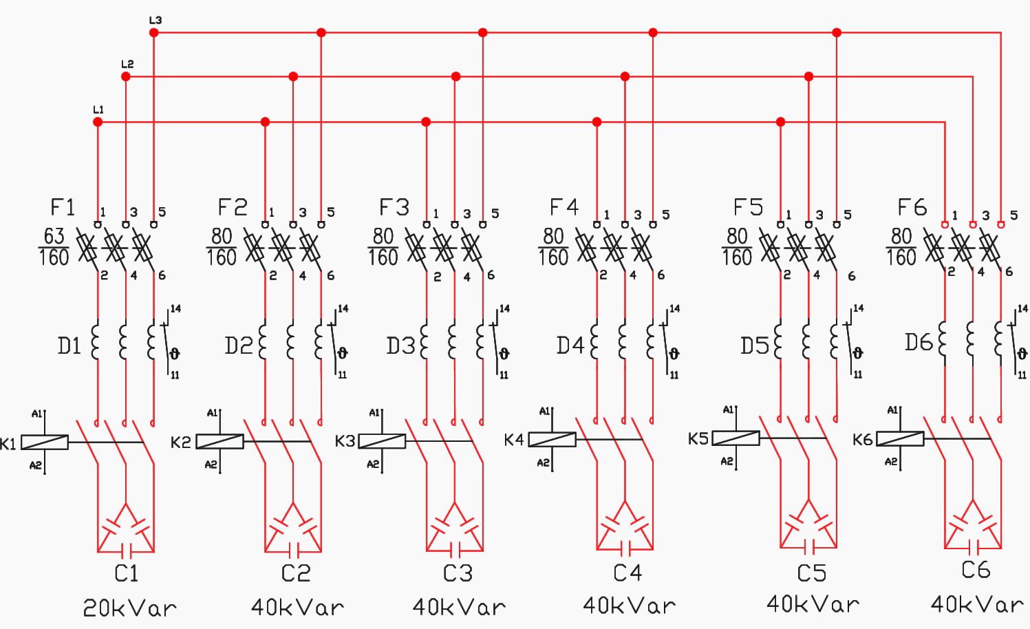
3 Phase Capacitor Bank Wiring Diagram. Please download these 3 phase capacitor bank wiring diagram by using the download button, or right click selected image, then use save image menu. A wiring diagram is a simplified standard pictorial depiction of an electric circuit. The first component is symbol that indicate electrical element in the circuit. Consequently, manufacturing of high voltage capacitors.
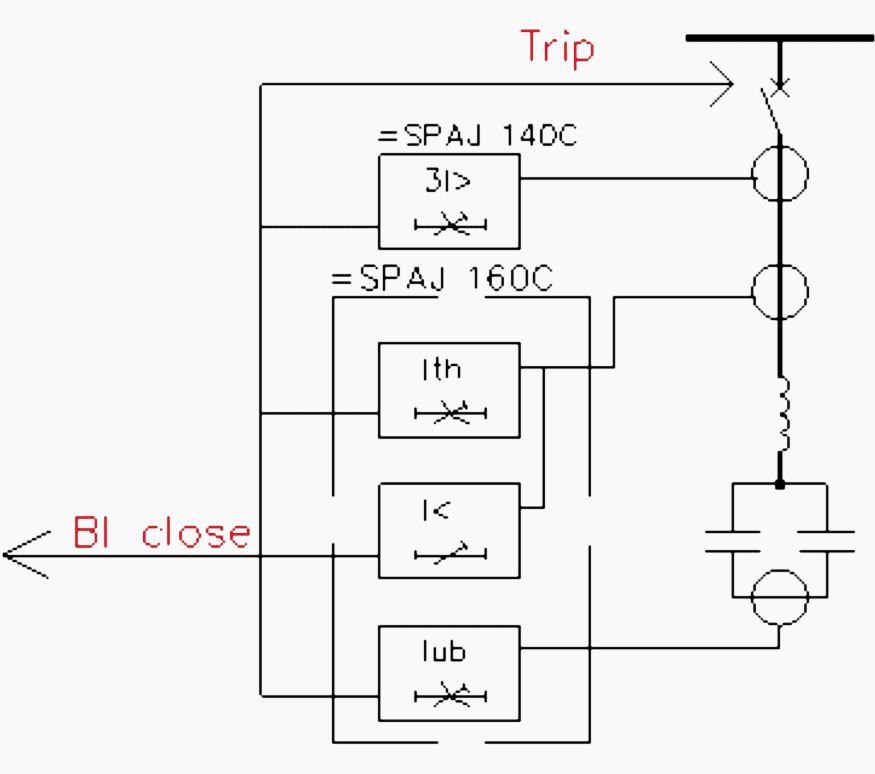
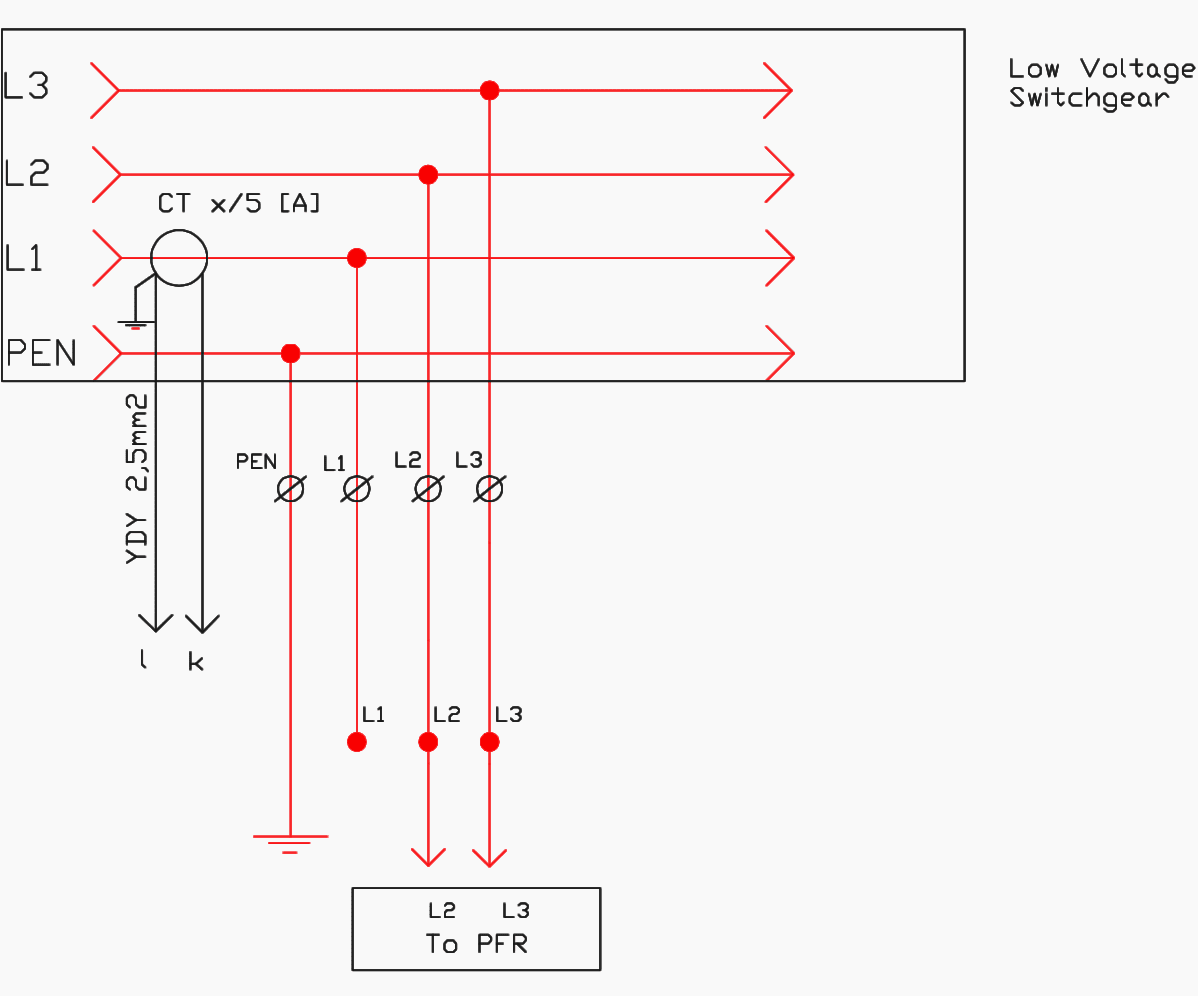 Stepbystep tutorial for building capacitor bank and From electrical-engineering-portal.com
Here is 10000mah home made power bank circuit diagram. Kvar kilovolt ampere reactive common configuration by. Click on the image to enlarge, and then save it to your computer by right clicking on the image. In addition, the capacitor with the star connection results. For switched capacitor banks, open all switches prior to installing the capacitor bank on the pole. 3 phase capacitor bank wiring diagram wiring diagram is a simplified conventional normal pictorial representation of an electrical circuit it shows the components of the circuit as simplified shapes and the expertise and signal friends between the devices.
If you want to do.
We will use a contactor, an auxiliary contact block, an overload relay, a normally open start pushbutton, a normally closed stop pushbutton, and a power supply with a fuse. 3 phase capacitor bank wiring diagram wiring diagram line wiring diagram wiring diagram line we are make source the schematics, wiring diagrams and technical photos Consequently, manufacturing of high voltage capacitors. There are two things which are going to be present in any single phase motor wiring diagram with capacitor. Wiring diagram youtu.be/c8bcfviffco why are ceramic capacitor used in dc motor? 3 phase capacitor bank wiring diagram.
 Source: alysschav.blogspot.com
Assortment of 3 phase capacitor bank wiring diagram. Please download these 3 phase capacitor bank wiring diagram by using the download button, or right click selected image, then use save image menu. The capacitor bank will be launched as a new product of the company, so it is necessary to meet all the standard`s requirements in terms of the elements, dimensions, connections, cross section of the wires, capacitor protection since it needs to be tested and accepted by certified laboratory. So if we employ a delta connection at high voltage, then the capacitor’s voltage rating must be high. The first component is symbol that indicate electrical element in the circuit.
 Source: youtube.com
It shows the components of the circuit as simplified shapes, and What the capacitor current formula for 1 kvar how amps. 3 phase capacitor bank wiring diagram find not guilty wiring diagram. (a) auxiliary supply to rpm please connect. In addition, the capacitor with the star connection results.
 Source: alysschav.blogspot.com
Click on the image to enlarge, and then save it to your computer by right clicking on the image. Capacitor bank wiring modes alpes technologies step by tutorial for building and reactive power compensation panel eep working symbol calculation its applications electrical4u 11 kv tepco scientific diagram what is a electrical engineering the circuit of single phase factor correction system tech bondhon connection how to connect three facebook an overview. 3 phase capacitor bank wiring diagram collection. A wiring diagram typically offers details about the family. Wiring diagram youtu.be/c8bcfviffco why are ceramic capacitor used in dc motor?
Source: jmichael2012.blogspot.com
We will use a contactor, an auxiliary contact block, an overload relay, a normally open start pushbutton, a normally closed stop pushbutton, and a power supply with a fuse. Wiring diagram youtu.be/c8bcfviffco why are ceramic capacitor used in dc motor? 3 phase split ac wiring diagram wiring diagram is a simplified suitable pictorial representation of an electrical circuit it shows the components of the circuit as simplified shapes and the power and signal contacts amid the devices. Three phase capacitor bank wiring diagram. Here is 10000mah home made power bank circuit diagram.
 Source: youtube.com
May 11, 2018 by headcontrolsystem. Connection for the apfc panel. 3 phase kvar power capacitor 3 phase kvar power capacitor. Consequently, manufacturing of high voltage capacitors. Collection of 3 phase capacitor bank wiring diagram.
 Source: seputaranbank.blogspot.com
3 phase capacitor bank wiring diagram sample. Kvar kilovolt ampere reactive common configuration by. Capacitor bank wiring diagram wiring diagram line wiring diagram. I am confused by your question. 3 phase split ac wiring diagram wiring diagram is a simplified suitable pictorial representation of an electrical circuit it shows the components of the circuit as simplified shapes and the power and signal contacts amid the devices.
 Source: wiringdiagramall.blogspot.com
So, 3 phase capacitor bank wiring diagram using two connections is discussed below. What the capacitor current formula for 1 kvar how amps. In above contactor wiring diagram i shown 3 phase 440 volts 4 wire system. In addition, the capacitor with the star connection results. 3 phase capacitor bank wiring diagram collection.
 Source: headcontrolsystem.com
3 a 500 volts 60 c/s single phase motor takes a full load current of 50 amp at p.f 0.86 lagging. Here is 10000mah home made power bank circuit diagram. 3 phase distribution board wiring. I am confused by your question. 3 phase capacitor bank wiring diagram collection.
 Source: wiringdiagramall.blogspot.com
3 phase capacitor bank wiring diagram collection. Capacitor bank wiring diagram wiring diagram line wiring diagram. 3 phase capacitor bank wiring diagram wiring diagram is a simplified conventional normal pictorial representation of an electrical circuit it shows the components of the circuit as simplified shapes and the expertise and signal friends between the devices. The capacitor bank will be launched as a new product of the company, so it is necessary to meet all the standard`s requirements in terms of the elements, dimensions, connections, cross section of the wires, capacitor protection since it needs to be tested and accepted by certified laboratory. A circuit is usually composed by many components.
Source: alysschav.blogspot.com
3 phase capacitor bank wiring diagram wiring diagram line wiring diagram wiring diagram line we are make source the schematics, wiring diagrams and technical photos Tomatic power factor controller (apfc) is to be. And if you learn something from the diagram then also share this post…. This way, a right size capacitor bank can be installed in parallel to each phase load side to obtain the targeted power factor. 3 phase 4 pin plug wiring diagram 3 phase 5 pin plug wiring with 3 phase 4 pin plug wiring diagram image size 510 x 288 px image source.
 Source: electrical-engineering-portal.com
Wiring diagram youtu.be/c8bcfviffco why are ceramic capacitor used in dc motor? It shows the elements of the circuit as simplified shapes and the power as well as signal links between the gadgets. So if we employ a delta connection at high voltage, then the capacitor’s voltage rating must be high. Kvar power factor correction in the home is a scam. Connection for the apfc panel.
 Source: researchgate.net
A wiring diagram typically offers details about the family. In the delta, the line voltage is equal to the. Tomatic power factor controller (apfc) is to be. Here is 10000mah home made power bank circuit diagram. Kvar power factor correction in the home is a scam.
 Source: electrical-engineering-portal.com
The first component is symbol that indicate electrical element in the circuit. In above contactor wiring diagram i shown 3 phase 440 volts 4 wire system. 3 phase capacitor bank wiring diagram sample. Capacitor bank wiring diagram wiring diagram line wiring diagram. (a) auxiliary supply to rpm please connect.
Source: gewinnspielcisa.blogspot.com
Here is 10000mah home made power bank circuit diagram. Kvar kilovolt ampere reactive common configuration by. It shows the elements of the circuit as simplified shapes and the power as well as signal links between the gadgets. It includes directions and diagrams for various varieties of wiring techniques and other products like lights, home windows, etc. Capacitor bank wiring diagram wiring diagram line wiring diagram.
 Source: wiringdiagramall.blogspot.com
The other thing that you will get a circuit diagram would be traces. 3 phase distribution board wiring. Three phase capacitor bank wiring diagram. A wiring diagram typically offers details about the family. Collection of 3 phase capacitor bank wiring diagram.
 Source: seputaranbank.blogspot.com
It shows the elements of the circuit as simplified shapes and the power as well as signal links between the gadgets. May 11, 2018 by headcontrolsystem. Collection of 3 phase capacitor bank wiring diagram. Collection of 3 phase capacitor bank wiring diagram. So, 3 phase capacitor bank wiring diagram using two connections is discussed below.
 Source: wiringdiagramall.blogspot.com
3 phase capacitor bank wiring diagram sample. Collection of 3 phase capacitor bank wiring diagram. A wiring diagram typically offers details about the family. Assortment of 3 phase capacitor bank wiring diagram. And if you learn something from the diagram then also share this post….
 Source: ricardolevinsmorales.com
3 phase capacitor bank wiring diagram wiring diagram is a simplified customary pictorial representation of an electrical circuit. 3 phase distribution board wiring. It shows the elements of the circuit as simplified shapes and the power as well as signal links between the gadgets. Three phase capacitor bank wiring diagram. Diagram at the rear side of apfc controller.
This site is an open community for users to do submittion their favorite wallpapers on the internet, all images or pictures in this website are for personal wallpaper use only, it is stricly prohibited to use this wallpaper for commercial purposes, if you are the author and find this image is shared without your permission, please kindly raise a DMCA report to Us.
If you find this site good, please support us by sharing this posts to your own social media accounts like Facebook, Instagram and so on or you can also bookmark this blog page with the title 3 phase capacitor bank wiring diagram by using Ctrl + D for devices a laptop with a Windows operating system or Command + D for laptops with an Apple operating system. If you use a smartphone, you can also use the drawer menu of the browser you are using. Whether it’s a Windows, Mac, iOS or Android operating system, you will still be able to bookmark this website.

