Your 2mdv4 capacitor wiring diagram images are ready in this website. 2mdv4 capacitor wiring diagram are a topic that is being searched for and liked by netizens now. You can Download the 2mdv4 capacitor wiring diagram files here. Get all free vectors.
If you’re searching for 2mdv4 capacitor wiring diagram pictures information connected with to the 2mdv4 capacitor wiring diagram interest, you have visit the ideal site. Our website always gives you suggestions for seeking the maximum quality video and image content, please kindly search and find more enlightening video content and images that fit your interests.
2mdv4 Capacitor Wiring Diagram. Wiring diagram not merely offers comprehensive illustrations of everything you can perform, but also the processes you ought to adhere to whilst performing so. For instance , in case a module will be powered up and it sends out a signal of half the voltage and the technician will not know this. A universal electric motor is designed to operate on either alternating current or direct current (ac/dc). Wire u2 is the connection to the run winding.
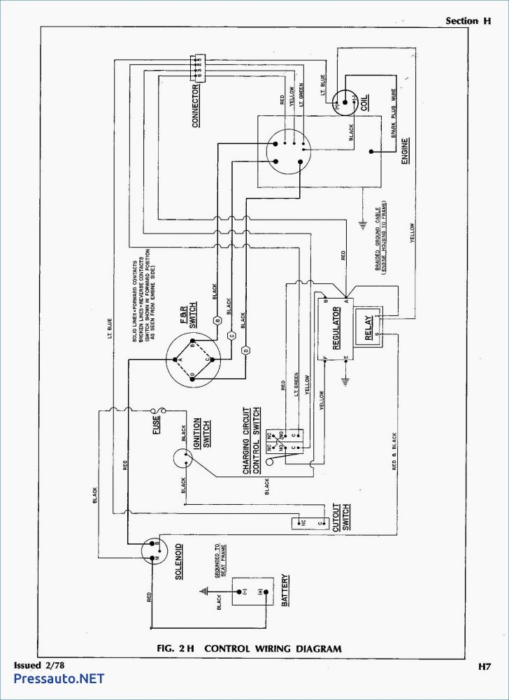
 Need wiring diagram for baldor vl3514t to dayton 2x441 From justanswer.com
The circuit diagram of the 555 timer in astable mode is shown below. Dealing with yellow, black, brown & brown/white stripe wires. It is a series wound motor. Motor 240 volt ac these diagrams apply to standard d/v alpha/beta series. Each component should be placed and linked to different parts in particular manner. Wiring of the distribution board , single phase, from energy meter to the main.
Click here to view a capacitor start motor circuit diagram for starting a single phase motor.
29.01.2019 29.01.2019 7 comments on wiring diagram compressor capacitor start capacitor run fractional h.p. Single phase capacitor start motor wiring diagram. Wire u2 is the connection to the run winding. Hvac shop talk podcast represents the blue collar boys and girls in the skilled trades, especially hvac. However, some people still struggle with the wiring part of the motor to the capacitor. To properly read a electrical wiring diagram, one offers to learn how the particular components in the system operate.
 Source: grainger.com
And the two stars which come out of the starting winding of the motor are mostly black wire. It uses a single pole double throw type transfer switch to impress a high voltage across the capacitor during start up. Wiring diagram for capacitor start motor techunick biz capacitors motor pioneer radio. How the heck do we connect to the new capacitor??? Fan is in but will not start.
 Source: ameer-diy-projects.blogspot.com
Dealing with yellow, black, brown & brown/white stripe wires. Click here to view a capacitor start motor circuit diagram for starting a single phase motor. September 8, 2021 on single phase motor wiring diagram with capacitor. Room air cooler wiring diagram # 2. Fan is in but will not start.
 Source: surplusindustrialequipment.com
If not, the arrangement will not work as it ought to be. It uses a single pole double throw type transfer switch to impress a high voltage across the capacitor during start up. You will be in a position to understand exactly once the assignments ought to be completed, that makes it much simpler to suit your needs to correctly manage. If 2 capacitors are required to obtain the necessary capacitance value individual capacitors are to. Fdl3514m product catalog baldor com.
Source: justanswer.com
For instance , in case a module will be powered up and it sends out a signal of half the voltage and the technician will not know this. Motor capacitor wiring diagram source: The wire color codes used in the motor capacitor wiring table above show the most common or standard conventions that might help you identify which wire in the electric motor wiring harness goes where and what it does. Rule of thumb on wiring the capacitor is: The schematic diagram for a permanent split capacitor motor is shown in fig.
 Source: askmehelpdesk.com
The circuit diagram of the 555 timer in astable mode is shown below. Herm on capacitor goes to the start winding on the compressor, fan on capacitor goes to brown fan wire that goes to the fan, and. Effectively read a electrical wiring diagram, one offers to find out how the components inside the method operate. To properly read a electrical wiring diagram, one offers to learn how the particular components in the system operate. Wiring diagram not merely offers comprehensive illustrations of everything you can perform, but also the processes you ought to adhere to whilst performing so.
 Source: s-selectricalsupply.com
8 9 2018 store of 3 phase capacitor bank wiring diagram a wiring diagram is a simplified okay pictorial depiction of an electric circuit it shows the elements of the circuit as simplified shapes and the capability as with ease as signal contacts along with the gadgets. Each component ought to be placed and linked to different parts in. A universal electric motor is designed to operate on either alternating current or direct current (ac/dc). Single phase capacitor start motor wiring diagram. For instance , if a module is usually powered up and it sends out a new signal of half the voltage and the technician will not know this, he would think he has a challenge, as.
 Source: ebay.com
The circuit diagram of the 555 timer in astable mode is shown below. Wire u1 is the common connection for both windings. Oval, 370v ac, 5, 2 13/16 in overall ht. These instructions will probably be easy to comprehend and implement. Notes to the table above:
This site is an open community for users to share their favorite wallpapers on the internet, all images or pictures in this website are for personal wallpaper use only, it is stricly prohibited to use this wallpaper for commercial purposes, if you are the author and find this image is shared without your permission, please kindly raise a DMCA report to Us.
If you find this site adventageous, please support us by sharing this posts to your preference social media accounts like Facebook, Instagram and so on or you can also bookmark this blog page with the title 2mdv4 capacitor wiring diagram by using Ctrl + D for devices a laptop with a Windows operating system or Command + D for laptops with an Apple operating system. If you use a smartphone, you can also use the drawer menu of the browser you are using. Whether it’s a Windows, Mac, iOS or Android operating system, you will still be able to bookmark this website.