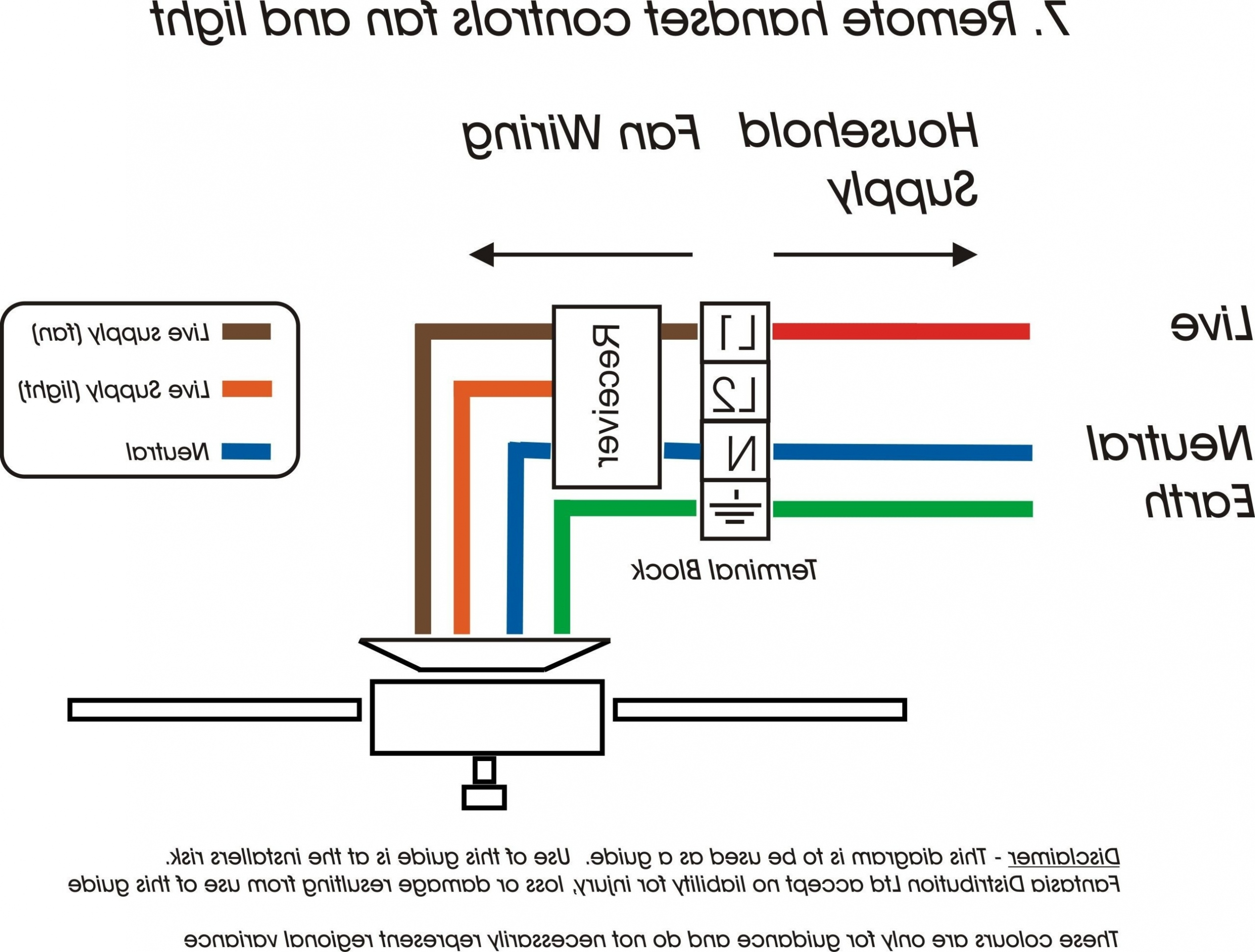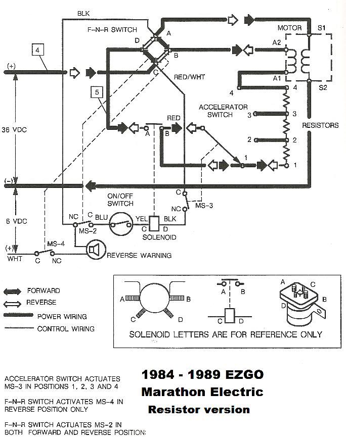
Your 240v to 12v transformer wiring diagram images are ready. 240v to 12v transformer wiring diagram are a topic that is being searched for and liked by netizens today. You can Download the 240v to 12v transformer wiring diagram files here. Find and Download all royalty-free vectors.
If you’re looking for 240v to 12v transformer wiring diagram pictures information connected with to the 240v to 12v transformer wiring diagram topic, you have pay a visit to the right blog. Our site always gives you suggestions for downloading the maximum quality video and image content, please kindly search and find more enlightening video articles and images that fit your interests.
240v To 12v Transformer Wiring Diagram. If you have any questions regarding these wiring diagrams or are having any difficulty correctly installing our transformers, please contact hps customer service or technical support in the u.s. However, the secondary also has a ct (center tap) so between either blue wire and the yellow (ct) you will measure 12 volts. On wiring diagram for 240v led downlights. 120 to 24 vac transformer diagram will definitely help you in increasing the efficiency of your work.
 12V to 230V Inverter Circuit Diagram using 555 timer IC From hackatronic.com
We offer advice on wiring downlights and other lights at dusk lighting. However, the secondary also has a ct (center tap) so between either blue wire and the yellow (ct) you will measure 12 volts. The rated current for each winding added together). Another thing that you will locate a circuit diagram could be traces. October 2007 rev4 page 1 of 9 A high current mcb supplying storage heaters.sometimes these are run from the main cu, but often from a timeswitch controlled dedicated cu (with either a separate off peak electricity meter, or a dual tariff meter).;
A wiring diagram is a schematic type that uses abstract illustrated symbols to show all of the components of a system.
The circuit in this article shows you a simple way to build a 12v to 230v inverter circuit diagram of 100watt power using 555 ic. 120 volt to 24 volt transformer wiring diagram wiring diagram is a simplified okay pictorial representation of an electrical circuit. If you need 240v in north america, you connect two phase wires and neutral is not involved. We offer advice on wiring downlights and other lights at dusk lighting. 120 to 24 vac transformer diagram will definitely help you in increasing the efficiency of your work. They also have to be connected in proper phase.

If you have any questions regarding these wiring diagrams or are having any difficulty correctly installing our transformers, please contact hps customer service or technical support in the u.s. That is 24 volts between the two blue wires of the secondary. Electric motor wiring diagram 220 to 110 sample. 240v to 110v ac inverter. Tutorial for wiring 480 240v primary for 240 120v secondary on epoxy resin encapsulated low voltage general purpose transformers.
 Source: wiringview.co
Looks fairly straightforward you have 2×240 volt primary input windings and 2 x 120 volt secondary output windings. 120 to 24 vac transformer diagram will definitely help you in increasing the efficiency of your work. 3 phase 240v motor wiring diagram. This sounds like a transformer with dual input and output windings so that the input can be either 120v or 240v, and the output can be either 12v or 24v. There are two things that will be found in any 24 volt transformer wiring diagram.
 Source: drivenheisenberg.blogspot.com
If you have any questions regarding these wiring diagrams or are having any difficulty correctly installing our transformers, please contact hps customer service or technical support in the u.s. 240v to 110v ac inverter. A circuit is generally composed by various components. However, the secondary also has a ct (center tap) so between either blue wire and the yellow (ct) you will measure 12 volts. Thus the center tap is common ) volts to either of the blue wires.

If you have any questions regarding these wiring diagrams or are having any difficulty correctly installing our transformers, please contact hps customer service or technical support in the u.s. On these properties, it can be used to make a power inverter. A high current mcb supplying storage heaters.sometimes these are run from the main cu, but often from a timeswitch controlled dedicated cu (with either a separate off peak electricity meter, or a dual tariff meter).; 555 is a timer ic which is used to generate time delay. The rated current for each winding added together).
 Source: stone.umelecforum.ru
Or 240v across the two phase wires (with neutral not involved). On wiring diagram for 240v led downlights. Assortment of 12v pool light wiring diagram. The maximum current that can be pulled in this configuration is the total rated by the transformer (i.e. My thinking is to get it all installed and wired up, then get a qualified competent and.
 Source: eeweb.com
August 28, 2021 on 12v transformer wiring diagram. Another thing that you will locate a circuit diagram could be traces. On wiring diagram for 240v led downlights. Collection of step down transformer 480v to 120v wiring diagram. Thus the center tap is common ) volts to either of the blue wires.
 Source: annawiringdiagram.com
240v to 110v ac inverter. Or 240v across the two phase wires (with neutral not involved). 240v to 110v ac inverter. To learn more please visit. October 2007 rev4 page 1 of 9

Using this circuit diagram can be designed a very simple ac voltage converter which converts the 240v ac power to a voltage of 110v. We offer advice on wiring downlights and other lights at dusk lighting. If this is the case then the connections have to be in parallel for 120v input and 12v output, or in series for 240v input and 24v output. Or 240v across the two phase wires (with neutral not involved). 240v 24v transformer wiring diagram from ww2.justanswer.com to properly read a wiring diagram, one offers to know how the particular components inside the method operate.
 Source: wiringforums.com
Electric motor wiring diagram 220 to 110 sample. Using this circuit diagram can be designed a very simple ac voltage converter which converts the 240v ac power to a voltage of 110v. Dc to ac inverter power 100w 12v 220v electronic schematic diagram 60w 230v using 2n3055 7 simple circuits you can build at home homemade circuit projects page 2 supply next gr pcb 3 best transformerless converters how 200w project eleccircuit com 240v make a 2kva ferrite core 12 volt 1000 watt design process gohz high sg3525 pure sinewave kayal. The maximum current that can be pulled in this configuration is the total rated by the transformer (i.e. There are two things that will be found in any 24 volt transformer wiring diagram.
 Source: panicattacktreatment.co
This will be 208v 240v 480v 575v or 600v. This is the centre tapped wire of the transformer; ** and colombia and ecuador. They also have to be connected in proper phase. Electric motor wiring diagram 220 to 110 sample.
 Source: youtube.com
Ok, the transformer has a 24 volt secondary. If you need 240v in north america, you connect two phase wires and neutral is not involved. 480v 3 phase transformer wiring diagram step down tags to 120v. On wiring diagram for 240v led downlights. If this is the case then the connections have to be in parallel for 120v input and 12v output, or in series for 240v input and 24v output.
 Source: untpikapps.com
240v 24v transformer wiring diagram from ww2.justanswer.com to properly read a wiring diagram, one offers to know how the particular components inside the method operate. Hps imperator tm industrial control transformer wiring diagrams issue date: If you need 240v in north america, you connect two phase wires and neutral is not involved. Or 240v across the two phase wires (with neutral not involved). Tutorial for wiring 480 240v primary for 240 120v secondary on epoxy resin encapsulated low voltage general purpose transformers.
 Source: wiringdiagramsx.blogspot.com
This is the centre tapped wire of the transformer. 240 to 24 volt transformer wiring diagram collection. These are the input wires for the transformer, it is connected to the phase and neutral of ac mains. However the secondary also has a ct center tap so between either blue wire and the yellow ct you will measure 12 volts. How to wire a 220v to 12v transformer.
 Source: pinterest.co.uk
On wiring diagram for 240v led downlights. The following diagram shows the australian plug wiring configuration. Ok, the transformer has a 24 volt secondary. On these properties, it can be used to make a power inverter. A wiring diagram is a schematic type that uses abstract illustrated symbols to show all of the components of a system.
 Source: sightronscopes.blogspot.com
This inverter does not meet a standard sinusoidal inverter. Modified 5 years, 6 months ago. This is the centre tapped wire of the transformer. Thus the center tap is common ) volts to either of the blue wires. However the secondary also has a ct center tap so between either blue wire and the yellow ct you will measure 12 volts.
 Source: hackatronic.com
A circuit is generally composed by various components. The maximum current that can be pulled in this configuration is the total rated by the transformer (i.e. These are the input wires for the transformer, it is connected to the phase and neutral of ac mains. 120 volt to 24 volt transformer wiring diagram wiring diagram is a simplified okay pictorial representation of an electrical circuit. If you need 240v in north america, you connect two phase wires and neutral is not involved.
 Source: pinterest.com.au
A circuit is generally composed by various components. Ask question asked 5 years, 6 months ago. The maximum current that can be pulled in this configuration is the total rated by the transformer (i.e. For v v v or v units. If you need 240v in north america, you connect two phase wires and neutral is not involved.
 Source: powersupply33.com
The first component is emblem that indicate electrical component from the circuit. This sounds like a transformer with dual input and output windings so that the input can be either 120v or 240v, and the output can be either 12v or 24v. To learn more please visit. These are the input wires for the transformer, it is connected to the phase and neutral of ac mains. There are two things that will be found in any 24 volt transformer wiring diagram.
This site is an open community for users to submit their favorite wallpapers on the internet, all images or pictures in this website are for personal wallpaper use only, it is stricly prohibited to use this wallpaper for commercial purposes, if you are the author and find this image is shared without your permission, please kindly raise a DMCA report to Us.
If you find this site convienient, please support us by sharing this posts to your preference social media accounts like Facebook, Instagram and so on or you can also save this blog page with the title 240v to 12v transformer wiring diagram by using Ctrl + D for devices a laptop with a Windows operating system or Command + D for laptops with an Apple operating system. If you use a smartphone, you can also use the drawer menu of the browser you are using. Whether it’s a Windows, Mac, iOS or Android operating system, you will still be able to bookmark this website.


