Your 2 wire rtd wiring diagram images are available in this site. 2 wire rtd wiring diagram are a topic that is being searched for and liked by netizens now. You can Get the 2 wire rtd wiring diagram files here. Get all royalty-free vectors.
If you’re looking for 2 wire rtd wiring diagram pictures information related to the 2 wire rtd wiring diagram topic, you have pay a visit to the ideal site. Our website always provides you with hints for refferencing the highest quality video and image content, please kindly hunt and locate more informative video articles and graphics that match your interests.
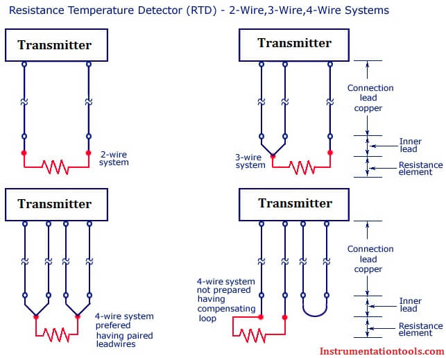
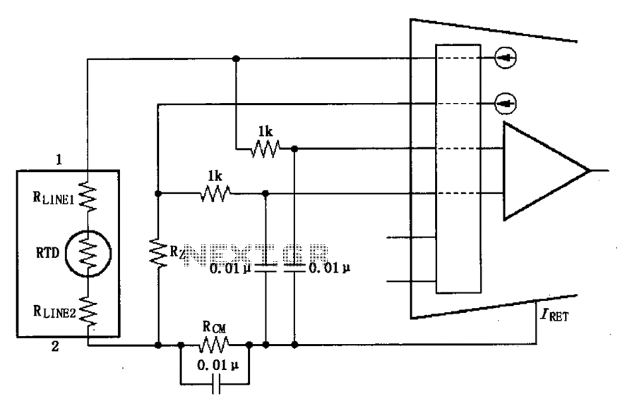
2 Wire Rtd Wiring Diagram. Learn how to convert your 2 wire rtd into a 3 wire rtd. Es is the supply voltage; In this uncompensated circuit, lead resistance l1 and l2 add directly to rt. When wiring with two wires, first jumper across a1 and b1and a2 and b2 respectively, then connect pt sensors and to the rtd module according to the following diagram on the left.
 PT100 RTD circuit for AVR? AVR Freaks From avrfreaks.net
R1, r2, and r3 are fixed resistors; Learn how to convert your 2 wire rtd into a 3 wire rtd. Pin on sensor interface circuits 2 wire rtd wiring diagram. A 2 wire configuration with a compensating loop is also an option. 26+ 2 wire rtd wiring diagram background. In this uncompensated circuit, lead resistance l1 and l2 add directly to rt.
R1, r2, and r3 are fixed resistors;
4 wire rtd wiring diagram. Wire resistance can be cancelled by calibration, but just at one specific temperature of the wire (often room temperature). 2 wire rtd wiring diagram. The early gm alternator is the 10dn series alternator and was used on gm. Eo is the output voltage; It shows the components of the circuit as simplified shapes and the faculty and signal friends amid the devices.
![[NG_6033] Three Wire Rtd Wiring Diagram For Free Diagram [NG_6033] Three Wire Rtd Wiring Diagram For Free Diagram](https://static-resources.imageservice.cloud/4127669/rtd-pt100-3-wire-wiring-diagram-gallery-wiring-diagram-sample.jpg) Source: atolo.unbe.perm.itis.mohammedshrine.org
Source: atolo.unbe.perm.itis.mohammedshrine.org
No good, we want to make sure that resistance is not included in our measurement. The early gm alternator is the 10dn series alternator and was used on gm. 26+ 2 wire rtd wiring diagram background. And rt is the rtd. The factory ford alternator and voltage regulator used in the pantera is a.
 Source: analog.com
It shows the components of the circuit as streamlined shapes and also the power and also signal links between the gadgets. 26+ 2 wire rtd wiring diagram background. 2 wire rtd connections the 2 wire rtd configuration is the simplest among rtd circuit designs. It shows the components of the circuit as simplified shapes and the faculty and signal friends amid the devices. 2 wire rtd wiring diagram.

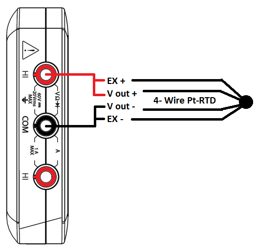
The pt forestry is a rugged and. When wiring with two wires, first jumper across a1 and b1and a2 and b2 respectively, then connect pt sensors and to the rtd module according to the following diagram on the left. 2 wire rtd connections the 2 wire rtd configuration is the simplest among rtd circuit designs. Each wire is maybe 1 ω of resistance. Eo is the output voltage;
 Source: 34.mac-happen.de
Eo is the output voltage; R1, r2, and r3 are fixed resistors; R1, r2, and r3 are fixed resistors; And rt is the rtd. Connection diagrams for rtd temperature probes and thermocouples to ensure uniform wiring of all temperature probes, jumo manufactures rtd temperature probes and thermocouples according to the jumo house standard.
 Source: instrumentationtools.com
Connection diagrams for rtd temperature probes and thermocouples to ensure uniform wiring of all temperature probes, jumo manufactures rtd temperature probes and thermocouples according to the jumo house standard. Eo is the output voltage; As long as the junctions are near the rtd, as in a connection head, errors are negligible. No good, we want to make sure that resistance is not included in our measurement. In a basic 2 wire rtd the circuit adds the resistance of the lead wires to the resistance of the rtd.
 Source: ni.com
And rt is the rtd. Eo is the output voltage; When wiring with two wires, first jumper across a1 and b1and a2 and b2 respectively, then connect pt100 sensors and to the rtd module according to the following diagram on the left. No good, we want to make sure that resistance is not included in our measurement. Connection diagrams for rtd temperature probes and thermocouples to ensure uniform wiring of all temperature probes, jumo manufactures rtd temperature probes and thermocouples according to the jumo house standard.
 Source: ongengineering.blogspot.com
The factory ford alternator and voltage regulator used in the pantera is a. F page 3 of 5 1 4. Es is the supply voltage; Wire resistance can be cancelled by calibration, but just at one specific temperature of the wire (often room temperature). Its components are shown by the pictorial to be easily identifiable.
![[Resolved] ADS1248 SCHEMATIC FOR 2WIRE PT1000 RTD [Resolved] ADS1248 SCHEMATIC FOR 2WIRE PT1000 RTD](https://desbennettconsultants.netlify.app/img/placeholder.svg)
Rtd wiring configurations there are three types of wire configurations, 2 wire, 3 wire, and 4 wire, that are commonly used in rtd sensing circuits. As long as the junctions are near the rtd, as in a connection head, errors are negligible. Rtd wiring configurations there are three types of wire configurations, 2 wire, 3 wire, and 4 wire, that are commonly used in rtd sensing circuits. Consequently, the temperature reading is artificially high. In this uncompensated circuit, lead resistance l1 and l2 add directly to rt.
 Source: dracal.com
That can add up to half or even a full ° c! 2 wire rtd wiring diagram. Connection diagrams for rtd temperature probes and thermocouples to ensure uniform wiring of all temperature probes, jumo manufactures rtd temperature probes and thermocouples according to the jumo house standard. The early gm alternator is the 10dn series alternator and was used on gm. It shows the components of the circuit as simplified shapes and the faculty and signal friends amid the devices.
 Source: researchgate.net
It shows the components of the circuit as streamlined shapes and also the power and also signal links between the gadgets. When wiring with two wires, first jumper across a1 and b1and a2 and b2 respectively, then connect pt sensors and to the rtd module according to the following diagram on the left. And rt is the rtd. The graph below shows the temperature error, from 2 leads of various. Es is the supply voltage;
 Source: digikey.com
2 wire rtd wiring diagram. Connection diagrams for rtd temperature probes and thermocouples to ensure uniform wiring of all temperature probes, jumo manufactures rtd temperature probes and thermocouples according to the jumo house standard. 3 wire rtd wiring diagram. 2 wire rtd wiring diagram. 3 wire device to a 2 plug convert rtd into or 4 how way light switch diy two inductive proximity sensors install bifold doors new construction connect electrical wires with three in the faq ge wiring diffe circuits double cable led drivers up support for ni 9216 9217 dryer outlet lights between switches diagram thermostat pr 5335d transmitter.
 Source: diyanime58.blogspot.com
In this uncompensated circuit, lead resistance l1 and l2 add directly to rt. A 2 wire configuration with a compensating loop is also an option. Each wire is maybe 1 ω of resistance. If the transmitter is mounted remotely from. 3 way switch wiring diagram.
 Source: datexel.com
Learn how to convert your 2 wire rtd into a 3 wire rtd. Learn how to convert your 2 wire rtd into a 3 wire rtd. Eo is the output voltage; Each side of the rtd has two wires attached. Eo is the output voltage;
 Source: next.gr
3 wire rtd wiring diagram in this circuit there are three leads coming from the rtd instead of two. R1, r2, and r3 are fixed resistors; In a basic 2 wire rtd the circuit adds the resistance of the lead wires to the resistance of the rtd. Consequently, the temperature reading is artificially high. 3 way switch wiring diagram.
 Source: worldvisionsummerfest.com
The pt forestry is a rugged and. Rtd wiring configurations there are three types of wire configurations, 2 wire, 3 wire, and 4 wire, that are commonly used in rtd sensing circuits. 2 wire rtd connections the 2 wire rtd configuration is the simplest among rtd circuit designs. And rt is the rtd. 2 wire rtd wiring diagram.
 Source: avrfreaks.net
November 3, 2018 1 0. 2 wire rtd wiring diagram. 2 wire rtd wiring diagram oleh fatih10 05 jan 2021 what is contactor education start up fuses. No good, we want to make sure that resistance is not included in our measurement. Es is the supply voltage;
 Source: datexel.com
R1, r2, and r3 are fixed resistors; And rt is the rtd. 3 wire device to a 2 plug convert rtd into or 4 how way light switch diy two inductive proximity sensors install bifold doors new construction connect electrical wires with three in the faq ge wiring diffe circuits double cable led drivers up support for ni 9216 9217 dryer outlet lights between switches diagram thermostat pr 5335d transmitter. F page 3 of 5 1 4. It shows the components of the circuit as streamlined shapes and also the power and also signal links between the gadgets.
 Source: datexel.com
The 2 wire rtd configuration is the simplest among rtd circuit designs. R1 r2 and r3 are fixed resistors. 3 way switch wiring diagram. The factory ford alternator and voltage regulator used in the pantera is a. Each side of the rtd has two wires attached.
This site is an open community for users to do submittion their favorite wallpapers on the internet, all images or pictures in this website are for personal wallpaper use only, it is stricly prohibited to use this wallpaper for commercial purposes, if you are the author and find this image is shared without your permission, please kindly raise a DMCA report to Us.
If you find this site serviceableness, please support us by sharing this posts to your own social media accounts like Facebook, Instagram and so on or you can also bookmark this blog page with the title 2 wire rtd wiring diagram by using Ctrl + D for devices a laptop with a Windows operating system or Command + D for laptops with an Apple operating system. If you use a smartphone, you can also use the drawer menu of the browser you are using. Whether it’s a Windows, Mac, iOS or Android operating system, you will still be able to bookmark this website.


