Your 2 wire pressure transmitter wiring diagram images are available. 2 wire pressure transmitter wiring diagram are a topic that is being searched for and liked by netizens now. You can Get the 2 wire pressure transmitter wiring diagram files here. Download all royalty-free photos and vectors.
If you’re looking for 2 wire pressure transmitter wiring diagram images information related to the 2 wire pressure transmitter wiring diagram interest, you have pay a visit to the right blog. Our website always gives you suggestions for seeing the highest quality video and image content, please kindly hunt and find more enlightening video content and images that fit your interests.
2 Wire Pressure Transmitter Wiring Diagram. Attach the sensor leads to the transmitter sensor terminals. Install field wiring conduit into the open transmitter conduit entry (for remote mounting) and feed wires into the transmitter housing. Pressure transducer and transmitter wiring explained. The model a pressure transmitter for general industrial applications is not only.
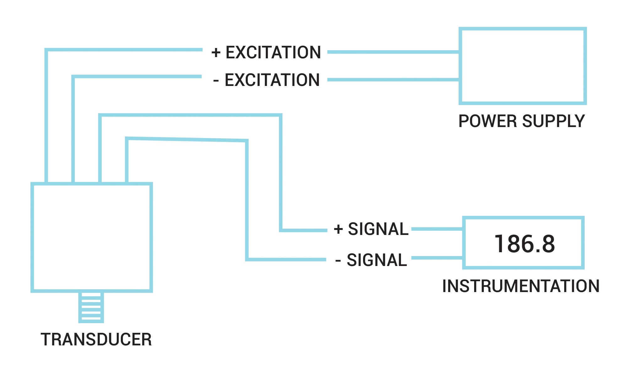 Pressure Transducers Installation and Use From omega.com
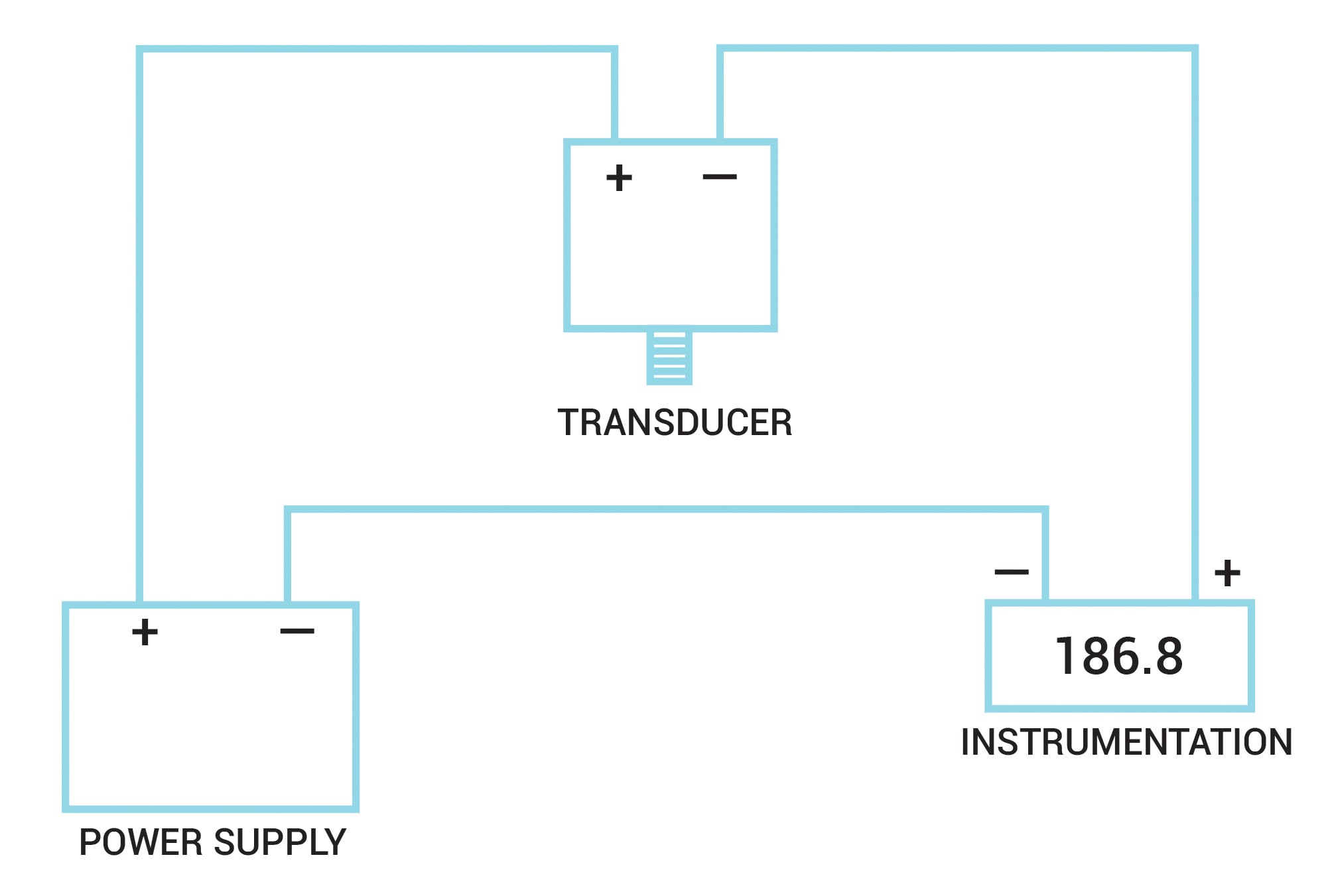
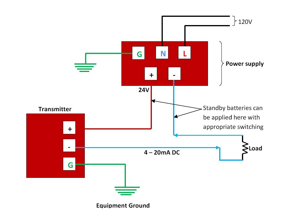
2 wire transmitter wiring diagram. A 2 wire transmitter has only 2 wires and is connected in series with the power supply and the plc. A first look at a circuit diagram could possibly be confusing, but if read a subway map, read schematics. Better protection against wiring errors. 2 a wire configuration and b 3 of rtd 5 scientific diagram three pressure transmitters way switch wiring how to switches hometips difference between 4 6 8 stepper motors ni antenna configurations source 1 thermostat electrical wires cable png 1200x800px area block brand cat crossover network computer examples layout floor plans local lan sample diagrams color. Mount the transmitter so that the drain/vent valves are oriented upward.
Automatic control 4 to 20ma signal generator circuit 20 ma potentiometer divize automation cur source brightwin 2 wire loop simulator diy detailed login instructions loginnote all about circuits convert 1 5v output edn 0 general electronics arduino forum a diagram of the digital pressure conditioner max1459 transmitter under 58756 next gr.
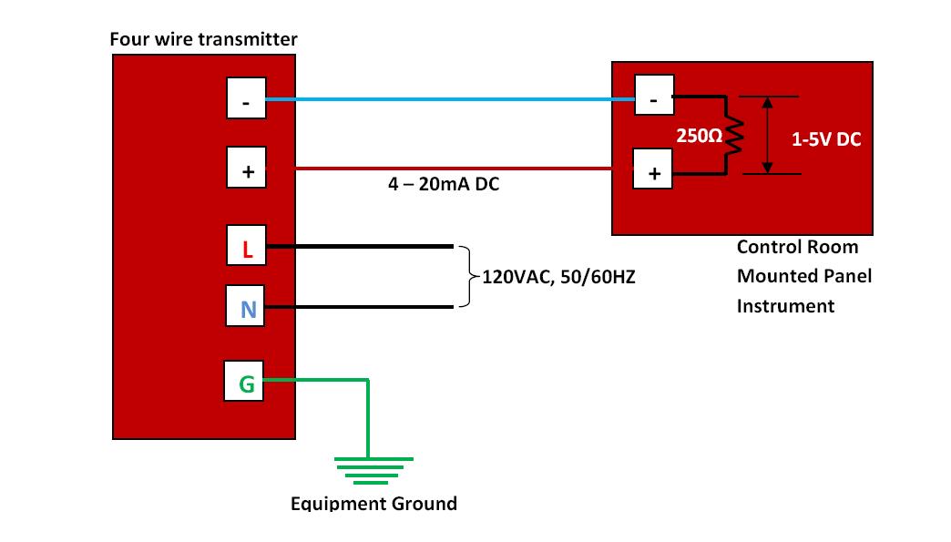
A 4 wire transmitter has 2 wires connected to a power supply and 2 signal wires connected to the plc. 2 a wire configuration and b 3 of rtd 5 scientific diagram three pressure transmitters way switch wiring how to switches hometips difference between 4 6 8 stepper motors ni antenna configurations source 1 thermostat electrical wires cable png 1200x800px area block brand cat crossover network computer examples layout floor plans local lan sample diagrams color. Brown green brown green white It reveals the parts of the circuit as streamlined shapes and the power as well as signal connections in between the gadgets. The schematic diagram below shows the wire transmitter configuration: Cable with 5 foot (1.5m) of cable and free ends circular connector m 12x1 5 pin.
Source: strawberry-sweet.blogspot.com
Mount the transmitter so that the drain/vent valves are oriented upward. This question is answered best from the viewpoint of the user: 2 wire pressure transmitter wiring diagram. This manual should be used in conjunction with the tronic line data sheets. These connection methods are of great concern to the instrument engineer technician.
 Source: sensorsone.com
Pull the field wiring leads into the terminal side of the housing. However, a separate power supply is also available as an option. Mount beside or above the taps. A first look at a circuit diagram could possibly be confusing, but if read a subway map, read schematics. The number of transmitters or devices that can be connected to a bus is primarily dependent on the power consumption of the transmitters or devices, the type of cable, the number of
 Source: ricardolevinsmorales.com
Attach the sensor leads to the transmitter sensor terminals. Place taps in the top or side of the line. Next is a resonance stage and the final stage built with a minimum 1w transistor which must have a heatsink. Pressure range 0…10 bar rel. It is a simulation diagram of the actual application in figure 2.
 Source: hestiahelper.blogspot.com
Place taps in the top or side of the line. Using a multimeter as the acquisition device, the sampling resistance is 250 ohms, the zero current is 4 ma, and the collected voltage is about 0.997 v (0.004 ma × 250 ohm = 1 v). 2 wire transmitter wiring diagram. Pull the field wiring leads into the terminal side of the housing. A beginner’s guide to circuit diagrams.
 Source: ricardolevinsmorales.com
It reveals the parts of the circuit as streamlined shapes and the power as well as signal connections in between the gadgets. Install field wiring conduit into the open transmitter conduit entry (for remote mounting) and feed wires into the transmitter housing. The number of transmitters or devices that can be connected to a bus is primarily dependent on the power consumption of the transmitters or devices, the type of cable, the number of Place taps to the side of the line. The schematic diagram below shows the wire transmitter configuration:
 Source: ricardolevinsmorales.com
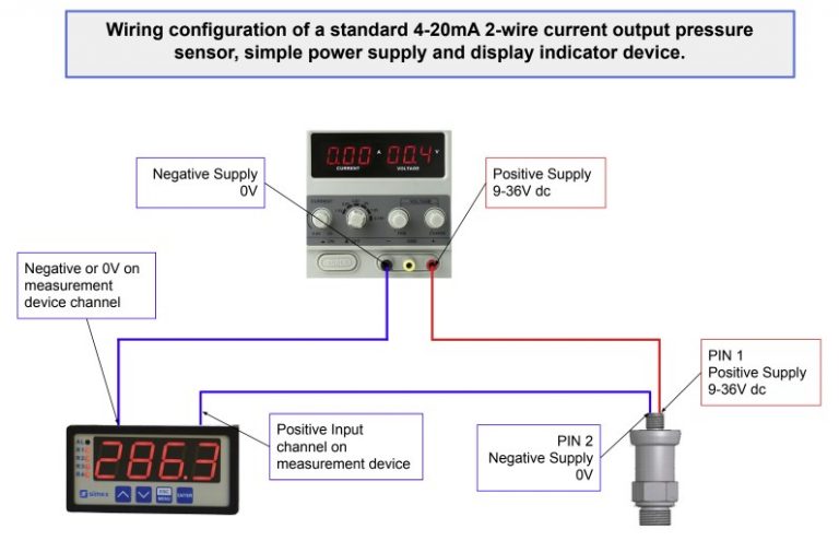
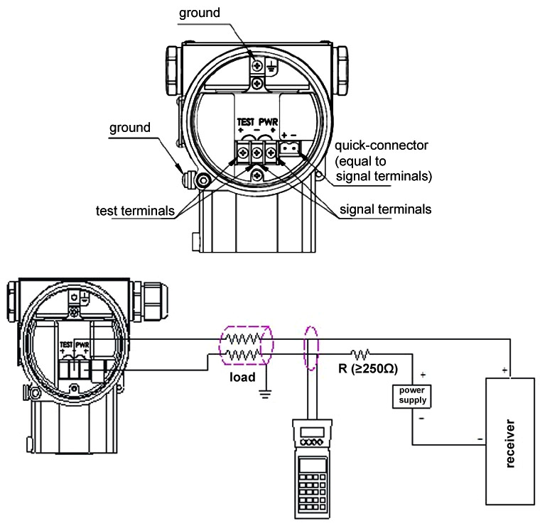
Better emc protection, since interferences can be filtered more easily. Better protection against wiring errors. Pressure transmitter calibration transmitter analog circuits how to apply today s electronic process transmitters pressure temperature flow and level are connected in different wire types or configurations. A 2 wire transmitter has only 2 wires and is connected in series with the power supply and the plc. The diagram below below shows a simple wiring configuration for current loop pressure transmitter.
 Source: omega.com
Attach the sensor leads to the transmitter sensor terminals. Pressure transducer and transmitter wiring explained. The wiring diagram is located inside the housing cover. Cable with 5 foot (1.5m) of cable and free ends circular connector m 12x1 5 pin. 2 wire pressure transmitter wiring diagram.
 Source: ato.com
This manual should be used in conjunction with the tronic line data sheets. Mount beside or below the taps. However, a separate power supply is also available as an option. These connection methods are of great concern to the instrument engineer technician. Automatic control 4 to 20ma signal generator circuit 20 ma potentiometer divize automation cur source brightwin 2 wire loop simulator diy detailed login instructions loginnote all about circuits convert 1 5v output edn 0 general electronics arduino forum a diagram of the digital pressure conditioner max1459 transmitter under 58756 next gr.
 Source: purple-itu-unggu.blogspot.com
Pressure transducer and transmitter wiring explained learn how to wire different transducers and transmitters to digital and analog plc input modules. The ceramic diaphragm is unbalanced in proportion to the pressure applied. Better protection against wiring errors. The wiring diagram is located inside the housing cover. The pressure transmitter model a offers excellent quality at an extremely x 1 , cable outlet 2 m;
 Source: instrumentationtools.com
Process connection g ¼ a din e, ¼ npt and others. Pressure range 0…10 bar rel. These connection methods are of great concern to the instrument engineer technician. Mount beside or below the taps. This question is answered best from the viewpoint of the user:
 Source: meacon.cn
Pressure range 0…10 bar rel. The wiring diagram is located inside the housing cover. This guidance note aims to outline these options. The model a pressure transmitter for general industrial applications is not only. Install field wiring conduit into the open transmitter conduit entry (for remote mounting) and feed wires into the transmitter housing.
 Source: wiringdiagram81.blogspot.com
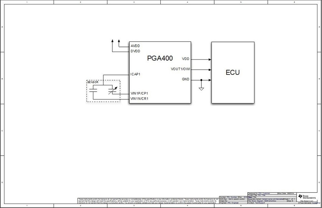
Process connection g ¼ a din e, ¼ npt and others. A beginner’s guide to circuit diagrams. Better emc protection, since interferences can be filtered more easily. The number of transmitters or devices that can be connected to a bus is primarily dependent on the power consumption of the transmitters or devices, the type of cable, the number of Depending on the sensor type used, the processed signal is provided as an analog output signal 4…20ma (2‐ wire) or 0…10v (3‐wire).
 Source: electronics.stackexchange.com
Next is a resonance stage and the final stage built with a minimum 1w transistor which must have a heatsink. The diagram below below shows a simple wiring configuration for current loop pressure transmitter. Attach the sensor leads to the transmitter sensor terminals. Place taps to the side of the line. It is a simulation diagram of the actual application in figure 2.
 Source: instrumentationtoolbox.com
Pressure range 0…10 bar rel. The ceramic diaphragm is unbalanced in proportion to the pressure applied. Pressure range 0…10 bar rel. Pull the field wiring leads into the terminal side of the housing. It is a simulation diagram of the actual application in figure 2.
 Source: wholefoodsonabudget.com
Using a multimeter as the acquisition device, the sampling resistance is 250 ohms, the zero current is 4 ma, and the collected voltage is about 0.997 v (0.004 ma × 250 ohm = 1 v). Pressure transmitter calibration transmitter analog circuits how to apply today s electronic process transmitters pressure temperature flow and level are connected in different wire types or configurations. Assortment of 2 wire pressure transducer wiring diagram. Pull the field wiring leads into the terminal side of the housing. Using a multimeter as the acquisition device, the sampling resistance is 250 ohms, the zero current is 4 ma, and the collected voltage is about 0.997 v (0.004 ma × 250 ohm = 1 v).
 Source: 3.criptoaldia.co
Mount beside or above the taps. Mount beside or above the taps. Automatic control 4 to 20ma signal generator circuit 20 ma potentiometer divize automation cur source brightwin 2 wire loop simulator diy detailed login instructions loginnote all about circuits convert 1 5v output edn 0 general electronics arduino forum a diagram of the digital pressure conditioner max1459 transmitter under 58756 next gr. Depending on the sensor type used, the processed signal is provided as an analog output signal 4…20ma (2‐ wire) or 0…10v (3‐wire). Attach the sensor leads to the transmitter sensor terminals.
Source: drivenheisenberg.blogspot.com
Install field wiring conduit into the open transmitter conduit entry (for remote mounting) and feed wires into the transmitter housing. Process connection g ¼ a din e, ¼ npt and others. The model a pressure transmitter for general industrial applications is not only. Using a multimeter as the acquisition device, the sampling resistance is 250 ohms, the zero current is 4 ma, and the collected voltage is about 0.997 v (0.004 ma × 250 ohm = 1 v). Pressure transducer and transmitter wiring explained learn how to wire different transducers and transmitters to digital and analog plc input modules.
 Source: wholefoodsonabudget.com
Process connection g ¼ a din e, ¼ npt and others. Brown green brown green white A 2 wire transmitter has only 2 wires and is connected in series with the power supply and the plc. This manual should be used in conjunction with the tronic line data sheets. The diagram below below shows a simple wiring configuration for current loop pressure transmitter.
This site is an open community for users to share their favorite wallpapers on the internet, all images or pictures in this website are for personal wallpaper use only, it is stricly prohibited to use this wallpaper for commercial purposes, if you are the author and find this image is shared without your permission, please kindly raise a DMCA report to Us.
If you find this site good, please support us by sharing this posts to your own social media accounts like Facebook, Instagram and so on or you can also bookmark this blog page with the title 2 wire pressure transmitter wiring diagram by using Ctrl + D for devices a laptop with a Windows operating system or Command + D for laptops with an Apple operating system. If you use a smartphone, you can also use the drawer menu of the browser you are using. Whether it’s a Windows, Mac, iOS or Android operating system, you will still be able to bookmark this website.


