
Your 2 wire microphone wiring diagram images are available in this site. 2 wire microphone wiring diagram are a topic that is being searched for and liked by netizens today. You can Get the 2 wire microphone wiring diagram files here. Get all royalty-free images.
If you’re looking for 2 wire microphone wiring diagram images information connected with to the 2 wire microphone wiring diagram keyword, you have pay a visit to the right blog. Our website frequently provides you with suggestions for seeing the maximum quality video and image content, please kindly hunt and locate more informative video content and graphics that match your interests.
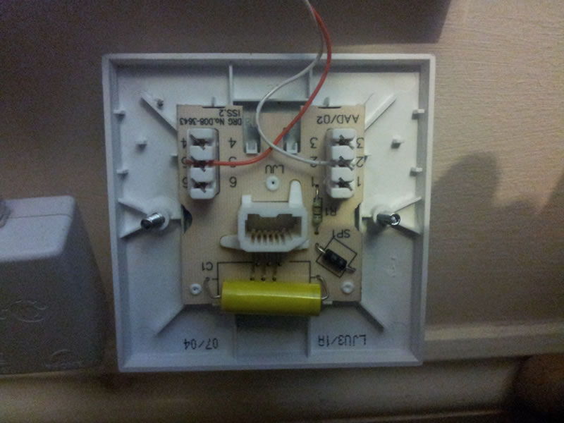
2 Wire Microphone Wiring Diagram. To convert to (m2) mm threaded connector and use all the following earpieces and headsets: 3 pin xlr wiring standard. For example, cobra 4 pin radios are wired 1) shield 2) audio 3) transmit 4) receive while midland 4 pin radios are wired 1) audio 2) shield 3) receive 4) transmit. Acet 702 (2 wire) 1) before replacing the handset make note of the wires to each terminal on the existing unit (an eas wi 3) some systems may have terminals 1 & 2 volt free button 3 5 common 6 input from panel 7 note :
 Short Break / The mystery of controlling the microphone From fbnews.jp
Inner copper wire is the microphone signal, outer sheath is the microphone ground. It is best to ohm out the wire, to make sure you wire it correctly. Push n buttons ruse ov supply 21809 21810 230v telephone 1 22220b telephone 2 22220b. In the above wiring diagram, an individual 12v dc transformer is used to power the microphone. The reddish one (which i�m assuming is the mono audio) and the copper one (which i�m assuming to be ground). Links to microphone wiring diagrams category is a curation of 30 web resources on , electro voice 664 wiring, kenwood pin connectors, microphone connections by g4wpw.
Have been given the task to take a sennheiser me2 and wire it up to a (like countryman) who publish wiring diagrams for their models to.
After you cut open the plastic insulating sheath you’ll find 5 separate wires: Electret mic (3 wire capsule) (read times) a look at a group called micbuilders (yahoo) tons of info, schematic and pix. 3 pin xlr wiring standard. Have been given the task to take a sennheiser me2 and wire it up to a (like countryman) who publish wiring diagrams for their models to. Wiring diagram acet 22200 (2 wire) 02 ch. The list below offers some cb microphone wiring information.
 Source: electronics.stackexchange.com
Microphone wiring can be a real pain if. 4 or 5 colors & shield here’s a case where the manufacturer gave you enough wires to make all the necessary switching functions. Red and green sheath with a copper wire inside: Same thing w9gb said dumbed down a bit, so even i can understand it. Inner copper wire is the microphone signal, outer sheath is the microphone ground.
 Source: diagramweb.net
Microphone wiring can be a real pain if. Drop cartridge and spacer into 65b1618 housing. This is a one transistor fm transmitter. Red and green sheath with a copper wire inside: Drop cartridge and housing assembly into the microphone case back and fasten with 30f1331a.
 data TX/RX for Raspberry Pi (flow") Source: flows.nodered.org
Source: flows.nodered.org
Solder according to the wiring diagram on the 55sh series ii data sheet. Not following the details will cause your household harm. The surrounding shield should be soldered to pin 1. Electret mic (3 wire capsule) (read times) a look at a group called micbuilders (yahoo) tons of info, schematic and pix. I�ve bought a new 3,5mm trs connector, but it appears to be stereo (as i guess it should be).
 Source: usbwiringdiagram.com
Let’s say the mike has the following wires in the cord: Electret mic (3 wire capsule) (read times) a look at a group called micbuilders (yahoo) tons of info, schematic and pix. Electret microphone cartridge wiring diagram mar 10, author topic: Confirm the audio leads as in the 4 wire instructions. On the microphone side, the 2.1mm plug simply pushes onto the power input of the microphone.
 Source: electronics.stackexchange.com
After you cut open the plastic insulating sheath you’ll find 5 separate wires: The microphone has a separate cable with 2 wires inside of it. On a 5 wire mic: I just got the lectrosonics smqv transmitter and want to wire a sennheiser me2 mic to the ta5f connector. Links to microphone wiring diagrams category is a curation of 30 web resources on , electro voice 664 wiring, kenwood pin connectors, microphone connections by g4wpw.
 Source: schematron.org
On a 5 wire mic: Push n buttons ruse ov supply 21809 21810 230v telephone 1 22220b telephone 2 22220b. Let’s say the mike has the following wires in the cord: I�ve bought a new 3,5mm trs connector, but it appears to be stereo (as i guess it should be). Acet 702 (2 wire) 1) before replacing the handset make note of the wires to each terminal on the existing unit (an eas wi 3) some systems may have terminals 1 & 2 volt free button 3 5 common 6 input from panel 7 note :
 Source: jaazz.me
(the rear view is the end you solder from) here are the connections on each pin: The reddish one (which i�m assuming is the mono audio) and the copper one (which i�m assuming to be ground). A certain wire has an appropriate pin number that is necessary to be followed. 2009 117 pm post subject. In the above wiring diagram, an individual 12v dc transformer is used to power the microphone.
 Source: schematron.org
A certain wire has an appropriate pin number that is necessary to be followed. Fasten 65b1617 cover to housing with 30b1336 screws. Finding the common wire is a 2 step process. Besure to twist the red/copper wire with the plain copper wire (the one wrapped over the white wire), these are your ground wires, they get soldered to the ring 2. Push n buttons ruse ov supply 21809 21810 230v telephone 1 22220b telephone 2 22220b.
 Source: usbwiringdiagram.com
Drop cartridge and housing assembly into the microphone case back and fasten with 30f1331a. Using a wire stripping tool remove about 3 cm 1 inch of the plastic insulation from each of the coloured wires to expose the copper as shown in the diagram see figure 4. The mic + connection seems fairly obvious too, on the ring of the mm. Astatic does not assume the responsibility of any damage to either the. 4 or 5 colors & shield here’s a case where the manufacturer gave you enough wires to make all the necessary switching functions.
 Source: youtube.com
To convert to (m2) mm threaded connector and use all the following earpieces and headsets: I just got the lectrosonics smqv transmitter and want to wire a sennheiser me2 mic to the ta5f connector. Let’s say the mike has the following wires in the cord: 3 pin xlr wiring diagram, cable wiring, etc. cable designed for being cut into standard mic cables may have 2 pairs of wire and a shield around the outside, in that case pair the colors together and make sure they go to the same pin number on each end. Finding the common wire is a 2 step process.
 Source: tacoma-wiring-diagram.blogspot.com
Not following the details will cause your household harm. To convert to (m2) mm threaded connector and use all the following earpieces and headsets: Microphone wiring can be a real pain if. Usually one or two of these wires will end up being unused and can be cut off when you solder on the plug. 3 pin xlr wiring diagram, cable wiring, etc. cable designed for being cut into standard mic cables may have 2 pairs of wire and a shield around the outside, in that case pair the colors together and make sure they go to the same pin number on each end.
 Source: schematron.org
Nisa on january 10, 2022. Red and green sheath with a copper wire inside: Nisa on january 10, 2022. Ece 2c laboratory manual in this second part of the lab#1 you will construct a microphone circuit using a compact electret condenser microphone cartridge. Links to microphone wiring diagrams category is a curation of 30 web resources on , electro voice 664 wiring, kenwood pin connectors, microphone connections by g4wpw.
 Source: usbwiringdiagram.com
Different manufacturers may use a different way to wire microphone. The fuel tank on the 1987 yamaha virago 750 holds about 23 gallons of gas. Electret microphone cartridge wiring diagram mar 10, author topic: A certain wire has an appropriate pin number that is necessary to be followed. In the above wiring diagram, an individual 12v dc transformer is used to power the microphone.
 Source: nencyluigi2.blogspot.com
Wiring diagram acet 22220 (2 wire) instructions. Acet 702 (2 wire) 1) before replacing the handset make note of the wires to each terminal on the existing unit (an eas wi 3) some systems may have terminals 1 & 2 volt free button 3 5 common 6 input from panel 7 note : Different manufacturers may use a different way to wire microphone. It is best to ohm out the wire, to make sure you wire it correctly. Electret mic (3 wire capsule) (read times) a look at a group called micbuilders (yahoo) tons of info, schematic and pix.
Source: fbnews.jp
Usually one or two of these wires will end up being unused and can be cut off when you solder on the plug. Same thing w9gb said dumbed down a bit, so even i can understand it. The above diagram shows you the pin numbering for both male and female xlr connectors, from the front and the rear view. Electret mic (3 wire capsule) (read times) a look at a group called micbuilders (yahoo) tons of info, schematic and pix. For example, cobra 4 pin radios are wired 1) shield 2) audio 3) transmit 4) receive while midland 4 pin radios are wired 1) audio 2) shield 3) receive 4) transmit.
 Source: usbwiringdiagram.com
Generally, a radio manufacturer will wire their microphones the same so that the microphones are interchangeable between their radios, however, this is not always the case. The red wire is right speaker and solders to ring 1. Here is a link to the schematics. Acet 702 (2 wire) 1) before replacing the handset make note of the wires to each terminal on the existing unit (an eas wi 3) some systems may have terminals 1 & 2 volt free button 3 5 common 6 input from panel 7 note : Have been given the task to take a sennheiser me2 and wire it up to a (like countryman) who publish wiring diagrams for their models to.
 Source: fbnews.jp
2009 117 pm post subject. 2 wire phone jack wiring diagram. In this project, we will go over how to build a complete microphone circuit with an electret microphone so that we can make recordings with it. Solder according to the wiring diagram on the 55sh series ii data sheet. It is best to ohm out the wire, to make sure you wire it correctly.
This site is an open community for users to do sharing their favorite wallpapers on the internet, all images or pictures in this website are for personal wallpaper use only, it is stricly prohibited to use this wallpaper for commercial purposes, if you are the author and find this image is shared without your permission, please kindly raise a DMCA report to Us.
If you find this site beneficial, please support us by sharing this posts to your favorite social media accounts like Facebook, Instagram and so on or you can also save this blog page with the title 2 wire microphone wiring diagram by using Ctrl + D for devices a laptop with a Windows operating system or Command + D for laptops with an Apple operating system. If you use a smartphone, you can also use the drawer menu of the browser you are using. Whether it’s a Windows, Mac, iOS or Android operating system, you will still be able to bookmark this website.


