Your 2 cell lipo battery wiring diagram images are available. 2 cell lipo battery wiring diagram are a topic that is being searched for and liked by netizens now. You can Download the 2 cell lipo battery wiring diagram files here. Download all free images.
If you’re looking for 2 cell lipo battery wiring diagram pictures information linked to the 2 cell lipo battery wiring diagram keyword, you have pay a visit to the ideal site. Our website always gives you hints for downloading the highest quality video and image content, please kindly search and locate more informative video content and images that fit your interests.
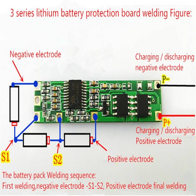
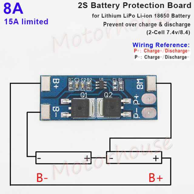
2 Cell Lipo Battery Wiring Diagram. Black wire to the minus of cell 2. This instructable goes through the wiring procedure for using all of the same electronics as if you used an arduino ramps grbl a obviously not both. According to previous, the lines at a 24 volt battery wiring diagram signifies wires. Below is a diagram to show how lipo battery cells are wired.
 Dna 250 Wiring Diagram Lipo From diagramweb.net
Strip the silicone rubber wires with the utility knife by rolling it. The diagram below shows how to create balancer y adaptors to balance and/or charge two batteries at the same time using one balancer unit. 18.5v battery = 5 cells x 3.7v= 5s battery. You can see two dc supply sources in the circuit. On a 2s lipo battery, that motor will spin around 25, rpm. Once our battery is soldered together, we need to measure the voltages across the series cells with a multimeter.
Since many electric motors in kayaks, bicycles, and scooters run on 24 volts this is a common.
Every one of us regularly used these all gadgets. The connection principle will be the same with a 3s as for the 4s. Additionally, the positive going to the b+ has a second wire going from positive to 2, 3, and 4. Never charge higher than 4.2v per cell. 3.7v battery = 1 cell x 3.7v= 1s battery. The wiring order is according to the provided schematic.
 Source: schematron.org
Since many electric motors in kayaks, bicycles, and scooters run on 24 volts this is a common. Injunction of two wires is usually indicated by black dot to the intersection of 2 lines. The system is wired as shown in the diagram below: Rated at 30c (33 amps) constant. Free shipping and up to 65 off.
 Source: fpvracer.lt
Below is a diagram to show how lipo battery cells are wired. Assuming the color codes are typical, where black is 0v and the red is the full output, check with a voltmeter i�ll bet you�ll see about 3.5v between the black and white, and about 7v between the black and red. Strip a small length of each wire and tin it. Particularly make sure you�ve soldered the wires onto the balance plug correctly as these are easy to mix up. Wiring a battery in series is a way to increase the voltage of a battery.
 Source: ex500-wiring-diagram.blogspot.com
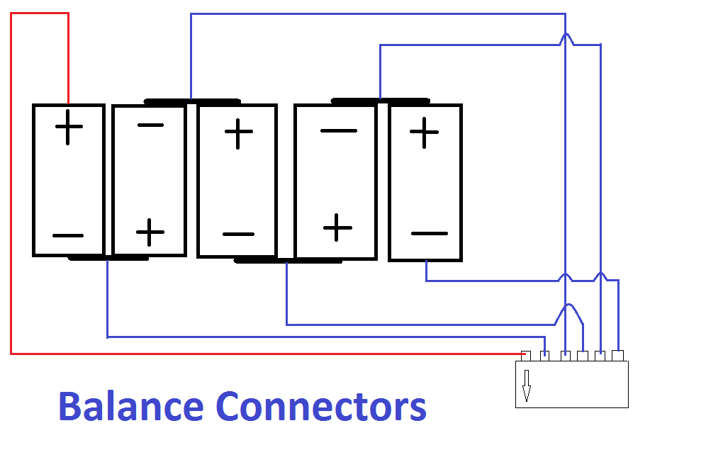
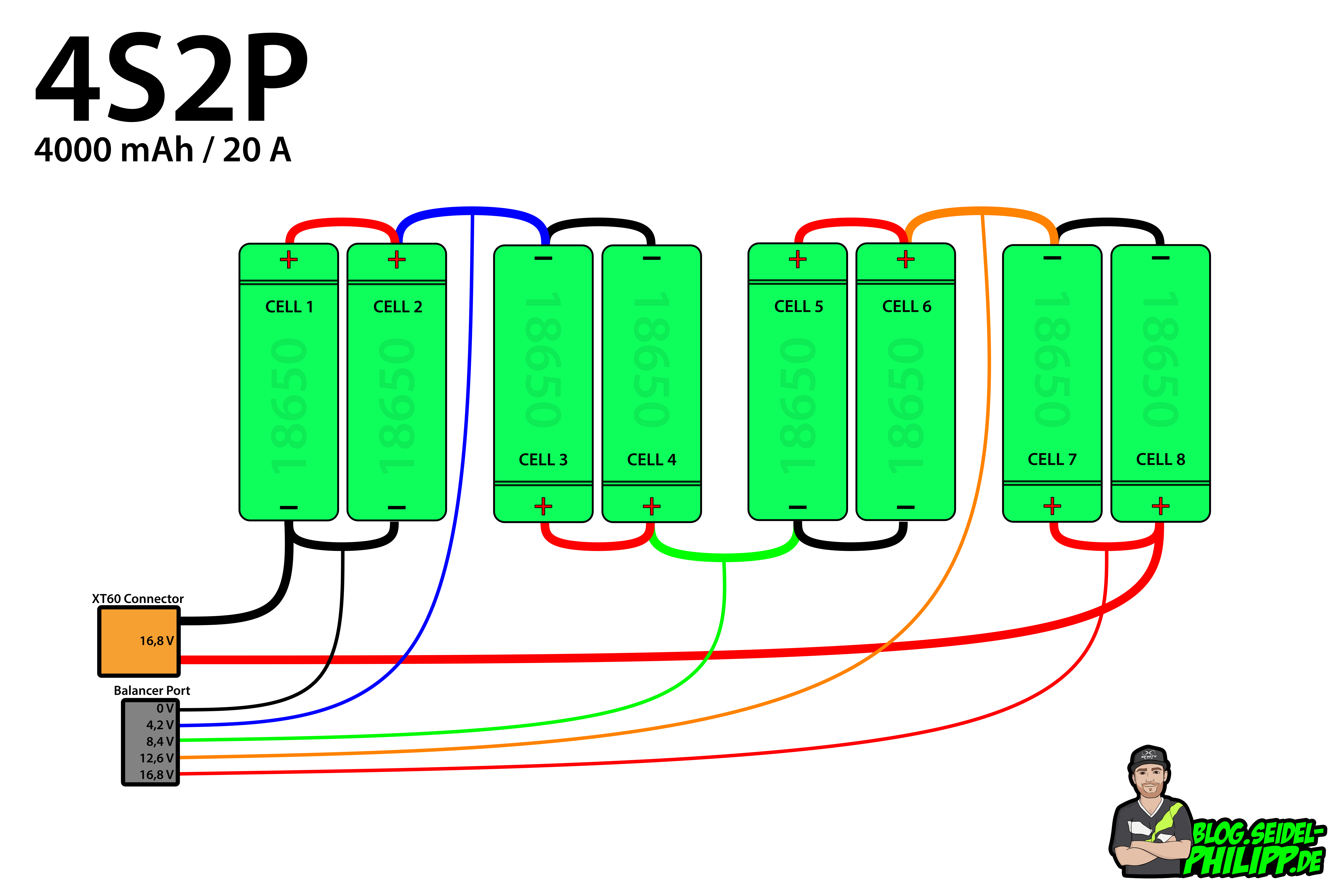
You should have 14.8 volts for battery positive, 3.7v volts, 7.4v volts, and 11.1 volts. The diagram below shows how to create balancer y adaptors to balance and/or charge two batteries at the same time using one balancer unit. The wiring order is according to the provided schematic. Jst xh 2p female to male 2 54mm connector terminal connection cable wire connectors connector power wire. Free shipping and up to 65 off.
Source: knoefchenfee.blogspot.com
8s lipo balancer cable silicone wire for a lifepo4 battery cell. One is a fixed 12v for the ics and the relay driver stages, second is the 4.2v for charging the lipo cells through the relay contacts. Black wire to the minus of cell 2. Its common for a lipo battery pack to have a tap in between every cell, so 3 wires makes sense for a 2s pack. It is not that hard to solder these small wires (just hold them down text diagram, to make it easier for you.
![]() Source: wiringschemas.blogspot.com
Source: wiringschemas.blogspot.com
Li ion battery charger circuit 3 7v use arduino for projects simple and pol cell diy lithium soldering mind high cur standalone ltc4054 how to build a 18650 booster module 7 v using lm358 mcp73831 po charge tp4056 circuits electronics charging many batteries from single lm317 fast 2 diagram mp2670 with protection mps 4 ne555 lm324. Rated at 30c (33 amps) constant. 18.5v battery = 5 cells x 3.7v= 5s battery. One for battery positive or cell #4, one for negative, cell #1, cell #2, and cell #3. Jst 1 2mm pitch ach achr 03v s connector wire harness harness car stereo wire.
 Source: cucv-wiring-diagram92.blogspot.com
14.8v battery = 4 cells x 3.7v= 4s battery. Black wire to the minus of cell 2. Arduino light sensor circuit using ldr arduino wiring diagram the diagram offers visual representation of an electric structure. Split the balancing cable and cut each individual wire reach the tabs without having slack. The wiring order is according to the provided schematic.
 Source: oscarliang.com
With a 60c (66 amps) burst rate. With the diodes in the collector circuit it forms the equivalent of the loadthat is the excess power will be dissipated as heat on these elements so the transistor may need a heat sink. So the more voltage you have, the faster you�re going to go. Li ion battery charger circuit 3 7v use arduino for projects simple and pol cell diy lithium soldering mind high cur standalone ltc4054 how to build a 18650 booster module 7 v using lm358 mcp73831 po charge tp4056 circuits electronics charging many batteries from single lm317 fast 2 diagram mp2670 with protection mps 4 ne555 lm324. 18.5v battery = 5 cells x 3.7v= 5s battery.
 Source: schematron.org
Every one of us regularly used these all gadgets. They are usually one cable more than the number of cell count as a rule of thumb though some balancer modules do utilize more cables at time. Here is the wiring diagram from the dna250c manual: Arduino light sensor circuit using ldr arduino wiring diagram the diagram offers visual representation of an electric structure. It is not that hard to solder these small wires (just hold them down text diagram, to make it easier for you.
 Source: wiringschemas.blogspot.com
The lead you show in yellow at the right side of the 2s balance plug is the negative lead. Particularly make sure you�ve soldered the wires onto the balance plug correctly as these are easy to mix up. Additionally, the positive going to the b+ has a second wire going from positive to 2, 3, and 4. The diagram below shows how to create balancer y adaptors to balance and/or charge two batteries at the same time using one balancer unit. One for battery positive or cell #4, one for negative, cell #1, cell #2, and cell #3.
 Source: schematron.org
Finally check and double check what you�ve done with the pictures and wiring diagram. Your text says your original is 3s, but your diagram shows a 4s on the left. Assuming the color codes are typical, where black is 0v and the red is the full output, check with a voltmeter i�ll bet you�ll see about 3.5v between the black and white, and about 7v between the black and red. 2 cell lipo battery wiring diagram. One for battery positive or cell #4, one for negative, cell #1, cell #2, and cell #3.
 Source: schematron.org
You can see two dc supply sources in the circuit. On a 3s, it will spin a whopping 38, rpm. This instructable goes through the wiring procedure for using all of the same electronics as if you used an arduino ramps grbl a obviously not both. Your text says your original is 3s, but your diagram shows a 4s on the left. Never charge higher than 4.2v per cell.
 Source: wiring.hpricorpcom.com
Arduino light sensor circuit using ldr arduino wiring diagram the diagram offers visual representation of an electric structure. It is not that hard to solder these small wires (just hold them down text diagram, to make it easier for you. You can see two dc supply sources in the circuit. So the more voltage you have, the faster you�re going to go. This called wiring a battery in series or in lithium batteries parallel.
Source: wiringschemas.blogspot.com
18.5v battery = 5 cells x 3.7v= 5s battery. 14.8v battery = 4 cells x 3.7v= 4s battery. The diagram below shows how to create balancer y adaptors to balance and/or charge two batteries at the same time using one balancer unit. Now let’s take a look at the other battery. This instructable goes through the wiring procedure for using all of the same electronics as if you used an arduino ramps grbl a obviously not both.
 Source: schematron.org
As shown in the following diagram, the proposed lipo battery balance charger circuit can be implemented rather effortlessly using a couple of ic stages. Molex 5264 2pin 2 54mm battery connector usb flash drive connectors connector. Free shipping and up to 65 off. With a 60c (66 amps) burst rate. Particularly make sure you�ve soldered the wires onto the balance plug correctly as these are easy to mix up.
 Source: wiringschemas.blogspot.com
On january 20, 2022 january 20, 2022 leave a comment on 2 cell lipo battery wiring diagram. Injunction of two wires is usually indicated by black dot to the intersection of 2 lines. Split the balancing cable and cut each individual wire reach the tabs without having slack. 18.5v battery = 5 cells x 3.7v= 5s battery. Making your own lipo packs is not difficult — it only requires a little care.
 Source: diagramweb.net
Never charge higher than 4.2v per cell. Li ion battery charger circuit 3 7v use arduino for projects simple and pol cell diy lithium soldering mind high cur standalone ltc4054 how to build a 18650 booster module 7 v using lm358 mcp73831 po charge tp4056 circuits electronics charging many batteries from single lm317 fast 2 diagram mp2670 with protection mps 4 ne555 lm324. With a 60c (66 amps) burst rate. Wiring a battery in series is a way to increase the voltage of a battery. Additionally, the positive going to the b+ has a second wire going from positive to 2, 3, and 4.
 Source: schematron.org
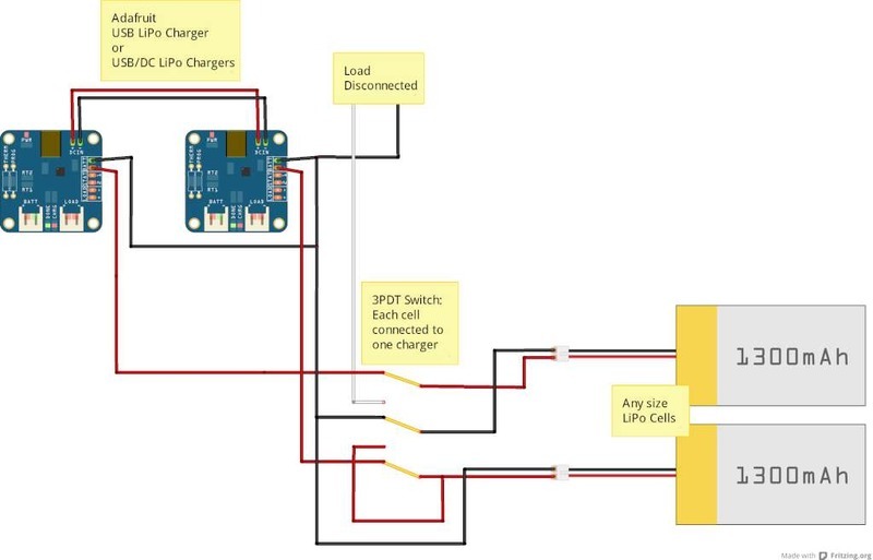
Jst 1 2mm pitch ach achr 03v s connector wire harness harness car stereo wire. For the fast charger, we use one charge controller per lipo cell. The diagram below shows how to create balancer y adaptors to balance and/or charge two batteries at the same time using one balancer unit. 3 long, 1 3/8 wide, 5/8 thick (75mm x 34mm x 16mm) weight: Split the balancing cable and cut each individual wire reach the tabs without having slack.
 Source: traxxas.com
14.8v battery = 4 cells x 3.7v= 4s battery. Batteries are for use in model aircraft rc vehicles only. In charge mode, the cells are disconnected from each other and from the load. Wiring a battery in series is a way to increase the voltage of a battery. You should have 14.8 volts for battery positive, 3.7v volts, 7.4v volts, and 11.1 volts.
This site is an open community for users to do submittion their favorite wallpapers on the internet, all images or pictures in this website are for personal wallpaper use only, it is stricly prohibited to use this wallpaper for commercial purposes, if you are the author and find this image is shared without your permission, please kindly raise a DMCA report to Us.
If you find this site convienient, please support us by sharing this posts to your favorite social media accounts like Facebook, Instagram and so on or you can also save this blog page with the title 2 cell lipo battery wiring diagram by using Ctrl + D for devices a laptop with a Windows operating system or Command + D for laptops with an Apple operating system. If you use a smartphone, you can also use the drawer menu of the browser you are using. Whether it’s a Windows, Mac, iOS or Android operating system, you will still be able to bookmark this website.


