Your 18 pulse vfd wiring diagram images are ready in this website. 18 pulse vfd wiring diagram are a topic that is being searched for and liked by netizens now. You can Get the 18 pulse vfd wiring diagram files here. Find and Download all royalty-free photos and vectors.
If you’re looking for 18 pulse vfd wiring diagram images information linked to the 18 pulse vfd wiring diagram topic, you have pay a visit to the ideal blog. Our site frequently provides you with suggestions for refferencing the maximum quality video and picture content, please kindly search and find more enlightening video content and images that match your interests.
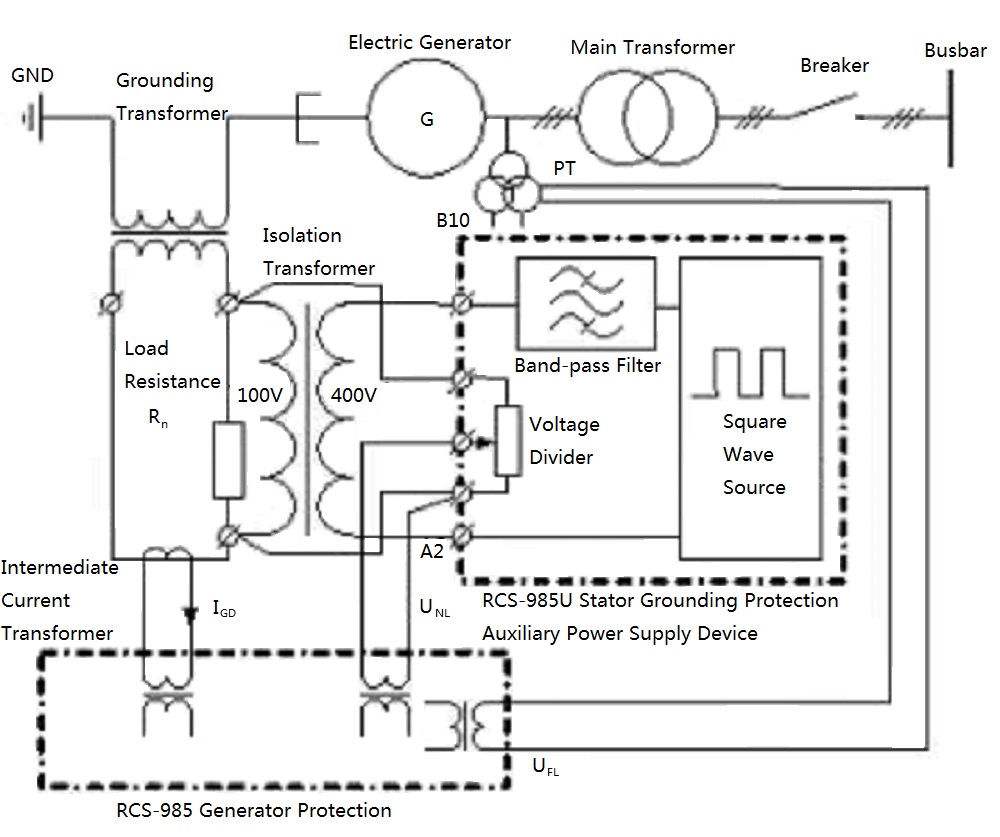
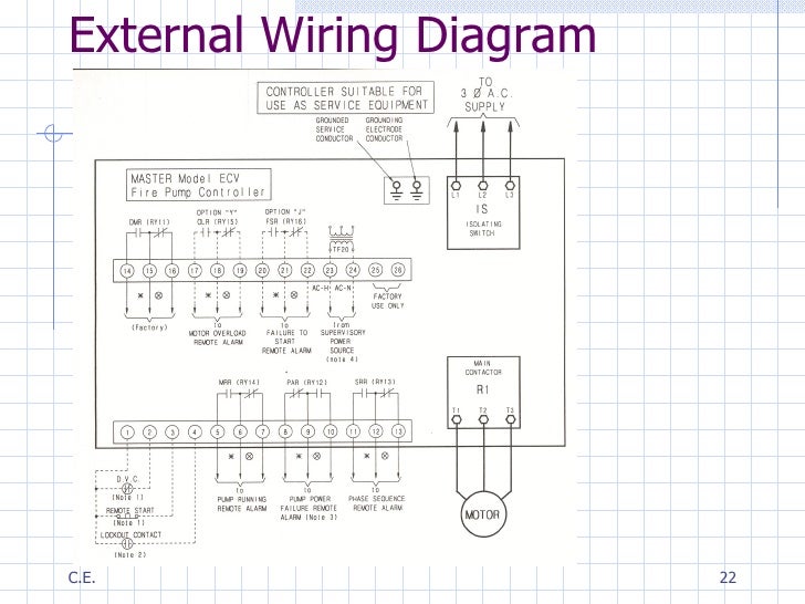
18 Pulse Vfd Wiring Diagram. It reveals the components of the circuit as simplified forms and also the power as well as signal connections in between the gadgets. The rest of page 8 of this plc wiring diagram is related to some interlocks or conditions and also the power to the fan of the electric motor. Lets examine a couple of typical scenarios commonly encountered the waveform of a typical 6 pulse vfd rectifier includes harmonics of the 5th 7th 11th 13th etc. The vastness of the options for the technology can be daunting at best and selecting the wrong vfd can create more problems than the ones that you are attempting to solve.
 24pulse DC supply for railway substation. Download From researchgate.net
Diode rectifier with large dc bus capacitors, used in the front ends of. Gk3000 series variable frequency drive (vfd) adopts speed sensorless. Impulse® g+/vg+ series 4 s4if interface card is designed to interface with 24/48/120 vac user input and output devices. I looked on the internet for information about and/or a schematic about the welder and found little information. Hello everyone, it could be me but i had a lot of trouble understanding how to get the remote switches on to my first vfd, and searching for help this time a. The following is a list of 8 considerations for selecting a variable frequency drive for your specific application:
In an ac drive there are two additional stages:
• when wiring bare wires, make sure they are perfectly arranged to go through the wiring holes. What is pulse number (6, 12, 18, 24) in drives? Main circuit wiring variable frequency drive wire input to terminals l1, l2 and l3 for three phase input. Enclosure fan2 on 30hp, 40hp, and 100hp at 480v. Heater is optional on all nema 3r. Because the line converter is configured with igbts, the converter is bidirectional.
 Source: schematron.org
This eliminates the need for an additional. G+/vg+ series 4 drives introduction: Main circuit wiring the vfd main circuit terminals shown as below figure. Make sure to connect the ground terminal to an appropriate safety ground. 9000x af drives user manual mn04001004e for more information visit:
 Source: electronics.stackexchange.com
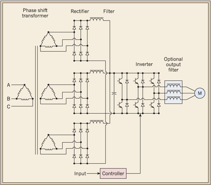
This eliminates the need for an additional. Ts1, enclosure fan1 standard on all nema 3r panels. Main circuit wiring variable frequency drive wire input to terminals l1, l2 and l3 for three phase input. • vfd’s produce specific harmonic frequencies with high magnitudes. These rectifiers are fed through a transformer with two secondary windings:
Source: matthewsvolvosite.com
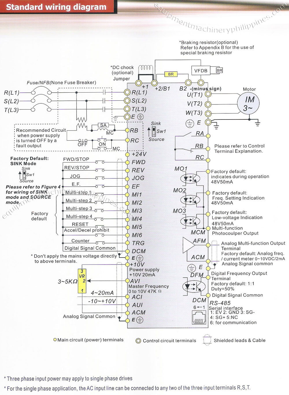
- the control circuit terminal uses a spring clamp terminal block: • when wiring bare wires, make sure they are perfectly arranged to go through the wiring holes. One ∆ and one y. Learn the basic wiring of variable frequency drives vfd with our electrician steve quist. (1) the vfd�s three phase ac input terminals (r/l1, s/l2, t/l3) the power line�s input terminals connect to 3 phase ac power through line protection or leakage protection breaker, it does not need to consider the connection of phase sequence.
 Source: researchgate.net
• vfd’s produce specific harmonic frequencies with high magnitudes. The vastness of the options for the technology can be daunting at best and selecting the wrong vfd can create more problems than the ones that you are attempting to solve. The vfds showed in the video are the d720s (230v single phase) and the d720 (230v three phase). I looked on the internet for information about and/or a schematic about the welder and found little information. G+/vg+ series 4 drives introduction:
 Source: researchgate.net
Lets examine a couple of typical scenarios commonly encountered the waveform of a typical 6 pulse vfd rectifier includes harmonics of the 5th 7th 11th 13th etc. I looked on the internet for information about and/or a schematic about the welder and found little information. Hy18d543b 3φ380v 50hz 18.5 32 40 18.5 hy002243b 3φ380v 50hz 22 37 47 22 hy003043b 3φ380v 50hz 30 52 65 30 hy003743b 3φ380v 50hz 37 64 80 37 hy004543b 3φ380v 50hz 45 72 91 45 hy005543b 3φ380v 50hz 55 84 110 55 !!! Main circuit wiring the vfd main circuit terminals shown as below figure. Learn the basic wiring of variable frequency drives vfd with our electrician steve quist.
 Source: researchgate.net
Application note ap0400076en vfd wiring best practices effective july 2014 2 eaton corporation www.eaton.com control wiring similar consideration need to be taken when looking at the control wiring. • tighten the wiring with a 2.5 mm width and 0.4 mm thickness slotted screwdriver. In an ac drive there are two additional stages: This eliminates the need for an additional. Set dip switches as needed.
Source: people.ece.cornell.edu
The vfds showed in the video are the d720s (230v single phase) and the d720 (230v three phase). • vfd’s produce specific harmonic frequencies with high magnitudes. Few days ago gohz made a 24v 2000w power inverter in home sharing some design schematics and circuit diagrams. 9000x af drives user manual mn04001004e for more information visit: • tighten the wiring with a 2.5 mm width and 0.4 mm thickness slotted screwdriver.
 Source: kewoacdrive.com
Hy18d543b 3φ380v 50hz 18.5 32 40 18.5 hy002243b 3φ380v 50hz 22 37 47 22 hy003043b 3φ380v 50hz 30 52 65 30 hy003743b 3φ380v 50hz 37 64 80 37 hy004543b 3φ380v 50hz 45 72 91 45 hy005543b 3φ380v 50hz 55 84 110 55 !!! Vfd start stop wiring diagram: Because the line converter is configured with igbts, the converter is bidirectional. The following is a list of 8 considerations for selecting a variable frequency drive for your specific application: Main circuit wiring variable frequency drive wire input to terminals l1, l2 and l3 for three phase input.
 Source: wiringdiagram.2bitboer.com
- the control circuit terminal uses a spring clamp terminal block: Because the line converter is configured with igbts, the converter is bidirectional. Gk3000 series variable frequency drive (vfd) adopts speed sensorless. In this video, we used the very popular mitsubishi d700 series vfd, showing single phase and three phase wiring instructions. The rest of page 8 of this plc wiring diagram is related to some interlocks or conditions and also the power to the fan of the electric motor.
 Source: people.ece.cornell.edu
Learn the basic wiring of variable frequency drives / vfd with our electrician steve quist. • vfd’s produce specific harmonic frequencies with high magnitudes. This eliminates the need for an additional. Main circuit wiring the vfd main circuit terminals shown as below figure. Vfd and their power and signal cabling section of this control panel wiring diagram.
 Source: researchgate.net
Vfd is a short form of variable frequency drive or variable voltage variable frequency drive.the vfds are working based on changing the input frequency and input voltage of the motor, we can change. Hy18d543b 3φ380v 50hz 18.5 32 40 18.5 hy002243b 3φ380v 50hz 22 37 47 22 hy003043b 3φ380v 50hz 30 52 65 30 hy003743b 3φ380v 50hz 37 64 80 37 hy004543b 3φ380v 50hz 45 72 91 45 hy005543b 3φ380v 50hz 55 84 110 55 !!! In this video, we used the very popular mitsubishi d700 series vfd, showing single phase and three phase wiring instructions. The rest of page 8 of this plc wiring diagram is related to some interlocks or conditions and also the power to the fan of the electric motor. Make sure to connect the ground terminal to an appropriate safety ground.
 Source: researchgate.net
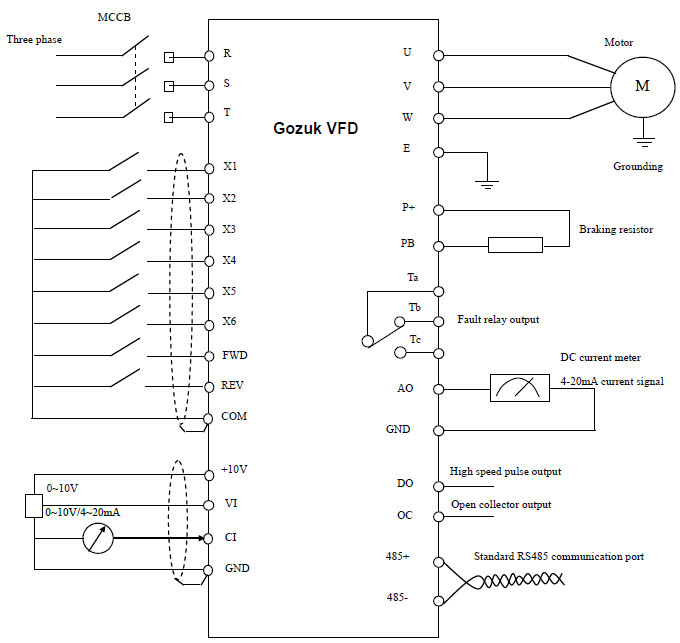
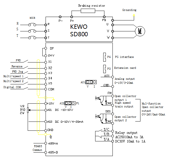
The rest of page 8 of this plc wiring diagram is related to some interlocks or conditions and also the power to the fan of the electric motor. This diagram shows the wires that supply power to the vfd the wires that provide voltage from the vfd to the motor and all the necessary input and output signals that the vfd needs for operation. The vfds showed in the video are the d720s (230v single phase) and the d720 (230v three phase). This eliminates the need for an additional. Learn the basic wiring of variable frequency drives vfd with our electrician steve quist.
 Source: filbuild.com
Make sure to connect the ground terminal to an appropriate safety ground. • when wiring bare wires, make sure they are perfectly arranged to go through the wiring holes. This diagram shows the wires that supply power to the vfd the wires that provide voltage from the vfd to the motor and all the necessary input and output signals that the vfd needs for operation. Gk3000 series variable frequency drive (vfd) adopts speed sensorless. Main circuit wiring the vfd main circuit terminals shown as below figure.
 Source: allabtinstru.blogspot.com
Because the line converter is configured with igbts, the converter is bidirectional. Vfd start stop wiring diagram: The following is a list of 8 considerations for selecting a variable frequency drive for your specific application: Set dip switches as needed. I am here with giving you a vfd start stop wiring diagram for running a vfd through panel board push button and keypad of the vfd (it is called hmi).
 Source: slideshare.net
Main circuit wiring variable frequency drive wire input to terminals l1, l2 and l3 for three phase input. What is pulse number (6, 12, 18, 24) in drives? Main circuit wiring variable frequency drive wire input to terminals l1, l2 and l3 for three phase input. One ∆ and one y. G+/vg+ series 4 drives introduction:
Source: articleelectrical.blogspot.com
Few days ago gohz made a 24v 2000w power inverter in home sharing some design schematics and circuit diagrams. Pulse a/1 leads as diagrammed below for encoders with pulse 2 leading, change diagram for these connections: We strongly recommend using a certified electrician. Gk3000 series variable frequency drive (vfd) adopts speed sensorless. • vfd’s produce specific harmonic frequencies with high magnitudes.
 Source: electronics.stackexchange.com
(1) the vfd�s three phase ac input terminals (r/l1, s/l2, t/l3) the power line�s input terminals connect to 3 phase ac power through line protection or leakage protection breaker, it does not need to consider the connection of phase sequence. Set dip switches as needed. 4) the control circuit terminal uses a spring clamp terminal block: Diodes shall be rated (devices) with. I looked on the internet for information about and/or a schematic about the welder and found little information.
 Source: ietresearch.onlinelibrary.wiley.com
Filtration and inversion back to ac. In this video, we used the very popular mitsubishi d700 series vfd, showing single phase and three phase wiring instructions. We strongly recommend using a certified electrician. Make sure to connect the ground terminal to an appropriate safety ground. Hello everyone, it could be me but i had a lot of trouble understanding how to get the remote switches on to my first vfd, and searching for help this time a.
This site is an open community for users to do submittion their favorite wallpapers on the internet, all images or pictures in this website are for personal wallpaper use only, it is stricly prohibited to use this wallpaper for commercial purposes, if you are the author and find this image is shared without your permission, please kindly raise a DMCA report to Us.
If you find this site beneficial, please support us by sharing this posts to your preference social media accounts like Facebook, Instagram and so on or you can also bookmark this blog page with the title 18 pulse vfd wiring diagram by using Ctrl + D for devices a laptop with a Windows operating system or Command + D for laptops with an Apple operating system. If you use a smartphone, you can also use the drawer menu of the browser you are using. Whether it’s a Windows, Mac, iOS or Android operating system, you will still be able to bookmark this website.


