Your 1746 ni4 wiring diagram images are available. 1746 ni4 wiring diagram are a topic that is being searched for and liked by netizens today. You can Get the 1746 ni4 wiring diagram files here. Download all royalty-free photos.
If you’re searching for 1746 ni4 wiring diagram images information linked to the 1746 ni4 wiring diagram interest, you have visit the right blog. Our website frequently gives you hints for downloading the maximum quality video and image content, please kindly hunt and locate more enlightening video articles and images that match your interests.
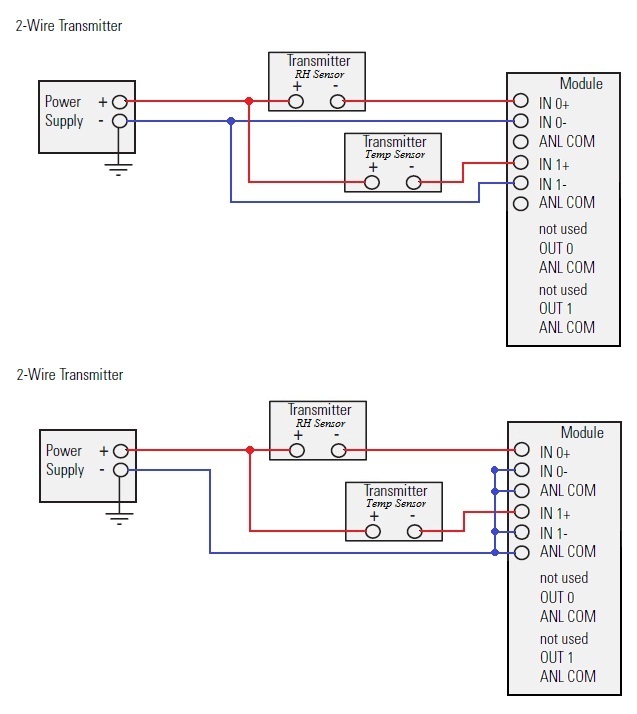
1746 Ni4 Wiring Diagram. It also provides diagnostic and troubleshooting information and application examples. 78 ( 1/4 page) manufacturer. • connect only one end of the cable shield to earth ground. Check that the module is operating correctly.
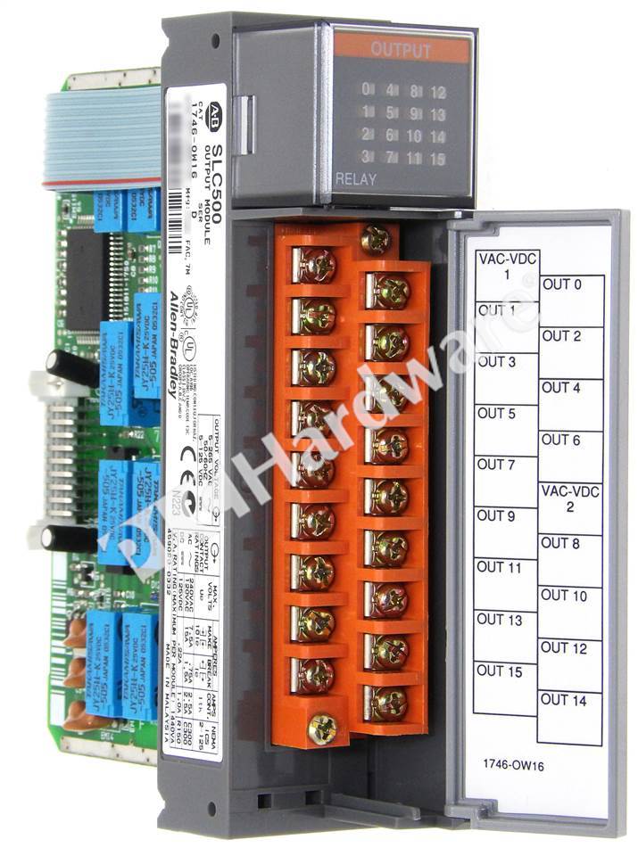 1746 OW16 PDF From 87a.info
Machine motion during system checkout can be hazardous to personnel. Match&start with 1746 ia16 total : This module is a resistance temperature detector (rtd) module that is used to interface rtd sensor to slc 500 control system. The input voltage or current is selectable per channel. Wiring diagrams 17 apply the octal filter label 6 apply the octal door label 6 removable terminal blocks 6 recovery from blown fuse/processor fault/processor shutdown 13 replacement fuse recommendations 13 replace fuses 14 • connect the shield drain wires for channels 0 to 3 to the top shield terminal.
78 ( 1/4 page) manufacturer.
This analog i/o module has 8 inputs and a backplane current (5 volts) of 200 milliamps. It contains the information you need to install, wire, and configure the module. • connect the shield drain wires for channels 0 to 3 to the top shield terminal. Additionally, the module accommodates 5 selectable data types; It features four (4) rtd inputs with each channel supporting a wide variety of rtd types. • use shielded communication cable (belden™ 8761) and keep length as short as possible.
 Source: plchardware.com
Machine motion during system checkout can be hazardous to personnel. It also provides diagnostic and troubleshooting information and application examples. The input voltage or current is selectable per channel. This analog i/o module has 8 inputs and a backplane current (5 volts) of 200 milliamps. Wiring diagrams 17 apply the octal filter label 6 apply the octal door label 6 removable terminal blocks 6 recovery from blown fuse/processor fault/processor shutdown 13 replacement fuse recommendations 13 replace fuses 14
 Source: plchardware.com
This module occupies single slot of the slc 500 chassis and compatible with fixed or modular style hardware. This analog i/o module has 8 inputs and a backplane current (5 volts) of 200 milliamps. Machine motion during system checkout can be hazardous to personnel. This module occupies single slot of the slc 500 chassis and compatible with fixed or modular style hardware. Additionally, the module accommodates 5 selectable data types;
 Source: plchardware.com
The input voltage or current is selectable per channel. Check that the module is operating correctly. 78 ( 1/4 page) manufacturer. It features four (4) rtd inputs with each channel supporting a wide variety of rtd types. Match&start with 1746 ia16 total :
 Source: plctalk.net
• connect only one end of the cable shield to earth ground. • connect only one end of the cable shield to earth ground. Chapter 4 (module operation and system considerations) catalog no. It contains the information you need to install, wire, and configure the module. Additionally, the module accommodates 5 selectable data types;
 Source: plchardware.com
Check that the module is operating correctly. Machine motion during system checkout can be hazardous to personnel. This module draws a backplane current of 35 ma at 5 volts and 85 ma at 24 volts, providing dip switches to manipulate channel 0. Wiring diagrams 17 apply the octal filter label 6 apply the octal door label 6 removable terminal blocks 6 recovery from blown fuse/processor fault/processor shutdown 13 replacement fuse recommendations 13 replace fuses 14 It also provides diagnostic and troubleshooting information and application examples.
 Source: plchardware.com
• connect the shield drain wires for channels 0 to 3 to the top shield terminal. Match&start with 1746 ia16 total : This module draws a backplane current of 35 ma at 5 volts and 85 ma at 24 volts, providing dip switches to manipulate channel 0. Wiring diagrams 17 apply the octal filter label 6 apply the octal door label 6 removable terminal blocks 6 recovery from blown fuse/processor fault/processor shutdown 13 replacement fuse recommendations 13 replace fuses 14 78 ( 1/4 page) manufacturer.
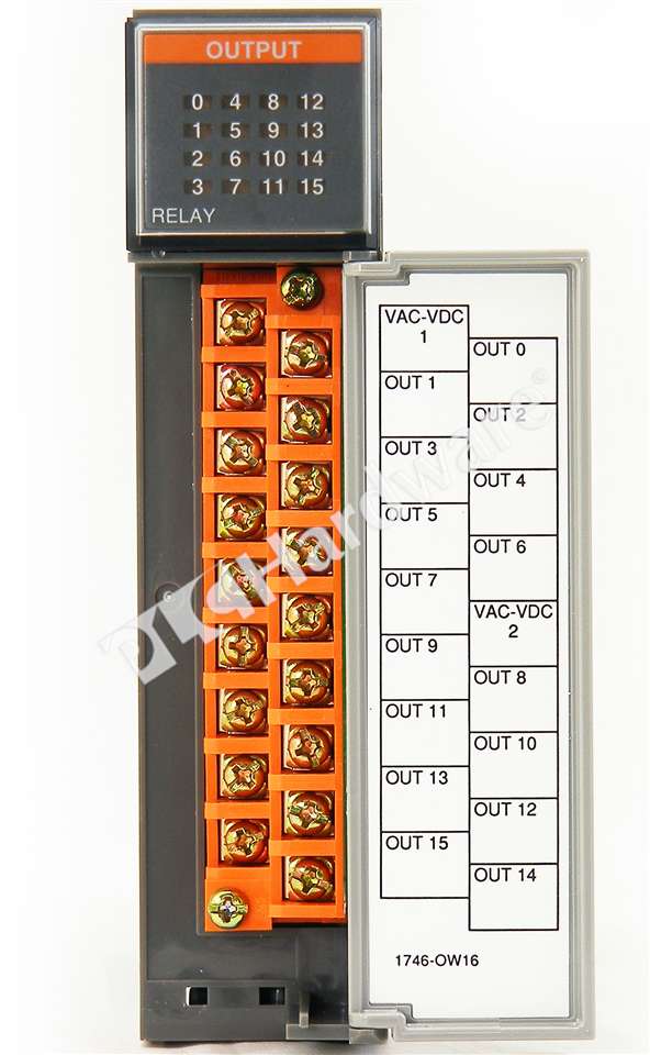 Source: plchardware.com
Additionally, the module accommodates 5 selectable data types; This module is a resistance temperature detector (rtd) module that is used to interface rtd sensor to slc 500 control system. It features four (4) rtd inputs with each channel supporting a wide variety of rtd types. • connect the shield drain wires for channels 0 to 3 to the top shield terminal. The input voltage or current is selectable per channel.
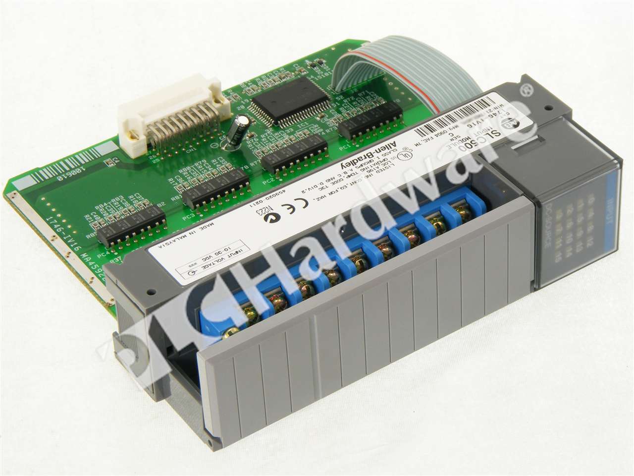 Source: plchardware.com
This module is a resistance temperature detector (rtd) module that is used to interface rtd sensor to slc 500 control system. Additionally, the module accommodates 5 selectable data types; This module occupies single slot of the slc 500 chassis and compatible with fixed or modular style hardware. It features four (4) rtd inputs with each channel supporting a wide variety of rtd types. Match&start with 1746 ia16 total :
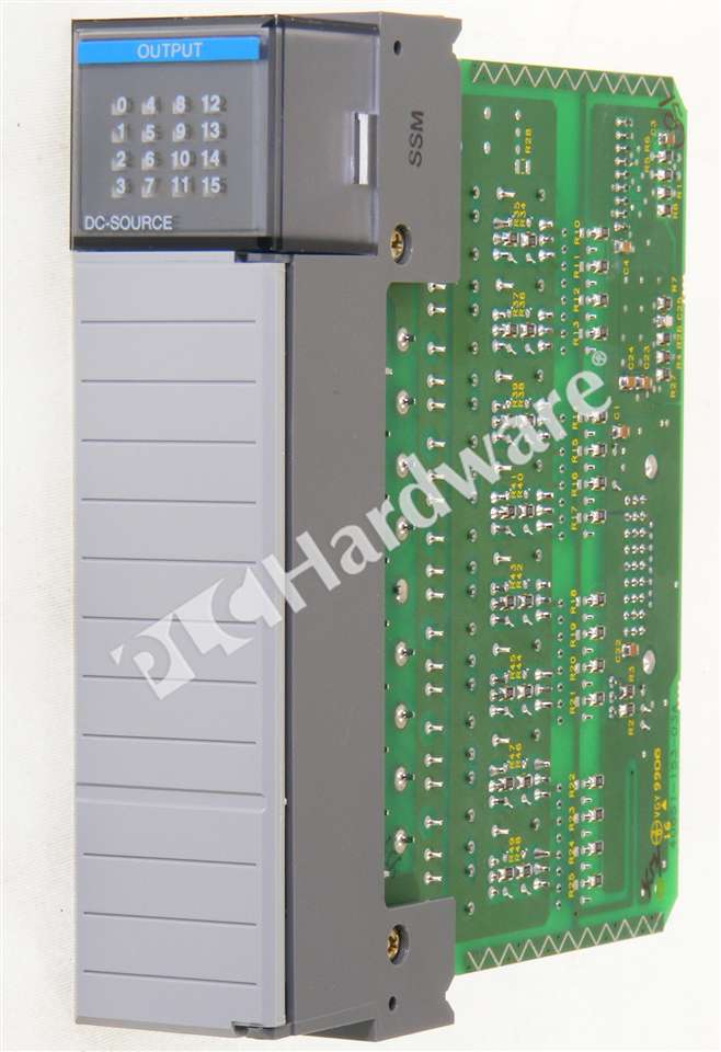 Source: plchardware.com
• connect only one end of the cable shield to earth ground. This module draws a backplane current of 35 ma at 5 volts and 85 ma at 24 volts, providing dip switches to manipulate channel 0. • connect the shield drain wires for channels 0 to 3 to the top shield terminal. Additionally, the module accommodates 5 selectable data types; The input voltage or current is selectable per channel.
 Source: plchardware.com
This module is a resistance temperature detector (rtd) module that is used to interface rtd sensor to slc 500 control system. It features four (4) rtd inputs with each channel supporting a wide variety of rtd types. This analog i/o module has 8 inputs and a backplane current (5 volts) of 200 milliamps. Check that the module is operating correctly. Chapter 4 (module operation and system considerations) catalog no.
 Source: plchardware.com
Match&start with 1746 ia16 total : • connect only one end of the cable shield to earth ground. • use shielded communication cable (belden™ 8761) and keep length as short as possible. It contains the information you need to install, wire, and configure the module. Additionally, the module accommodates 5 selectable data types;
 Source: plchardware.com
78 ( 1/4 page) manufacturer. Chapter 4 (module operation and system considerations) catalog no. Machine motion during system checkout can be hazardous to personnel. Check that the module is operating correctly. Additionally, the module accommodates 5 selectable data types;
 Source: 87a.info
Wiring diagrams 17 apply the octal filter label 6 apply the octal door label 6 removable terminal blocks 6 recovery from blown fuse/processor fault/processor shutdown 13 replacement fuse recommendations 13 replace fuses 14 The input voltage or current is selectable per channel. This module is a resistance temperature detector (rtd) module that is used to interface rtd sensor to slc 500 control system. It contains the information you need to install, wire, and configure the module. 78 ( 1/4 page) manufacturer.
 Source: plchardware.com
• connect only one end of the cable shield to earth ground. It contains the information you need to install, wire, and configure the module. Chapter 4 (module operation and system considerations) catalog no. The input voltage or current is selectable per channel. Match&start with 1746 ia16 total :
 Source: ebay.com
This module occupies single slot of the slc 500 chassis and compatible with fixed or modular style hardware. Match&start with 1746 ia16 total : It contains the information you need to install, wire, and configure the module. • connect the shield drain wires for channels 0 to 3 to the top shield terminal. The input voltage or current is selectable per channel.
 Source: plchardware.com
• use shielded communication cable (belden™ 8761) and keep length as short as possible. This module occupies single slot of the slc 500 chassis and compatible with fixed or modular style hardware. Chapter 4 (module operation and system considerations) catalog no. • connect only one end of the cable shield to earth ground. Machine motion during system checkout can be hazardous to personnel.
 Source: answersplc.com
• use shielded communication cable (belden™ 8761) and keep length as short as possible. Wiring diagrams 17 apply the octal filter label 6 apply the octal door label 6 removable terminal blocks 6 recovery from blown fuse/processor fault/processor shutdown 13 replacement fuse recommendations 13 replace fuses 14 • connect the shield drain wires for channels 0 to 3 to the top shield terminal. It contains the information you need to install, wire, and configure the module. 78 ( 1/4 page) manufacturer.
 Source: plchardware.com
It features four (4) rtd inputs with each channel supporting a wide variety of rtd types. • connect the shield drain wires for channels 0 to 3 to the top shield terminal. This analog i/o module has 8 inputs and a backplane current (5 volts) of 200 milliamps. It also provides diagnostic and troubleshooting information and application examples. This module is a resistance temperature detector (rtd) module that is used to interface rtd sensor to slc 500 control system.
This site is an open community for users to submit their favorite wallpapers on the internet, all images or pictures in this website are for personal wallpaper use only, it is stricly prohibited to use this wallpaper for commercial purposes, if you are the author and find this image is shared without your permission, please kindly raise a DMCA report to Us.
If you find this site serviceableness, please support us by sharing this posts to your preference social media accounts like Facebook, Instagram and so on or you can also bookmark this blog page with the title 1746 ni4 wiring diagram by using Ctrl + D for devices a laptop with a Windows operating system or Command + D for laptops with an Apple operating system. If you use a smartphone, you can also use the drawer menu of the browser you are using. Whether it’s a Windows, Mac, iOS or Android operating system, you will still be able to bookmark this website.


