Your 1734 ow4 wiring diagram images are ready in this website. 1734 ow4 wiring diagram are a topic that is being searched for and liked by netizens today. You can Find and Download the 1734 ow4 wiring diagram files here. Download all free photos.
If you’re looking for 1734 ow4 wiring diagram pictures information connected with to the 1734 ow4 wiring diagram keyword, you have pay a visit to the ideal blog. Our website always provides you with hints for downloading the maximum quality video and picture content, please kindly surf and locate more enlightening video articles and graphics that fit your interests.
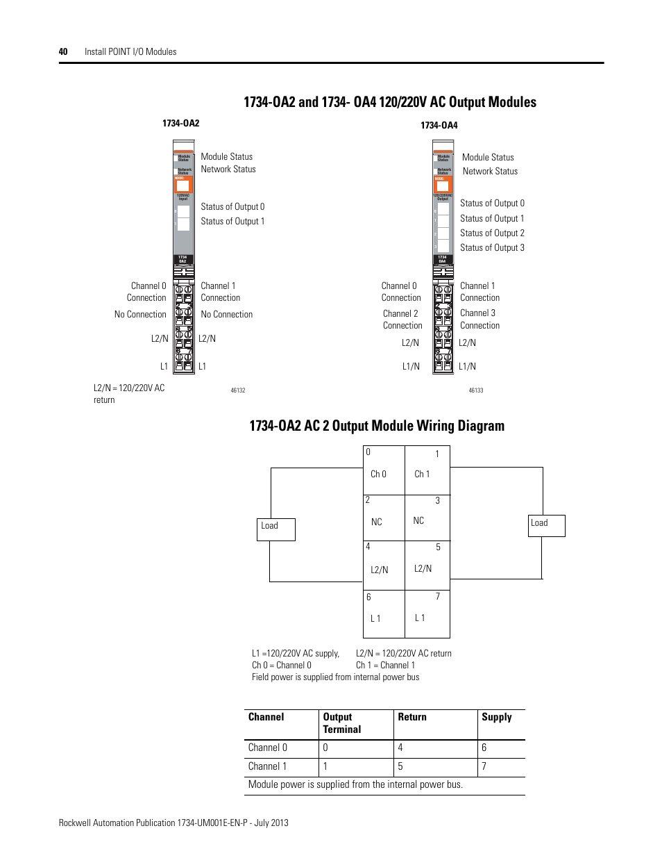
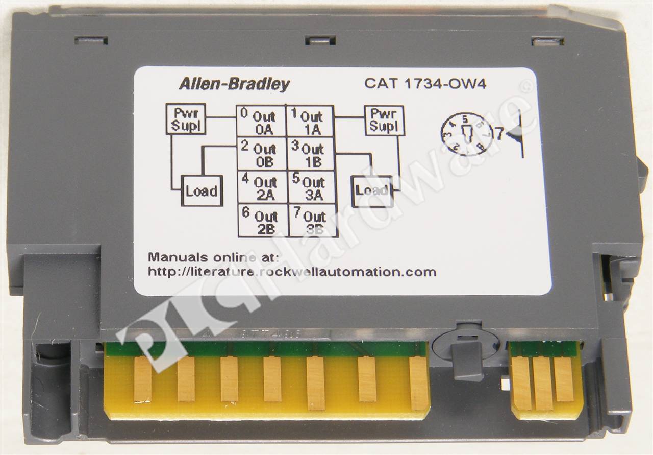
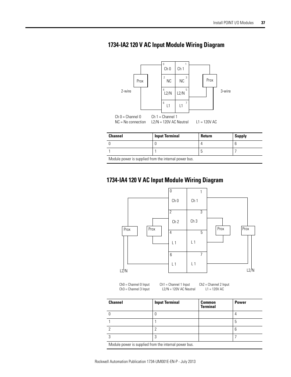
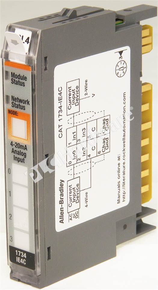
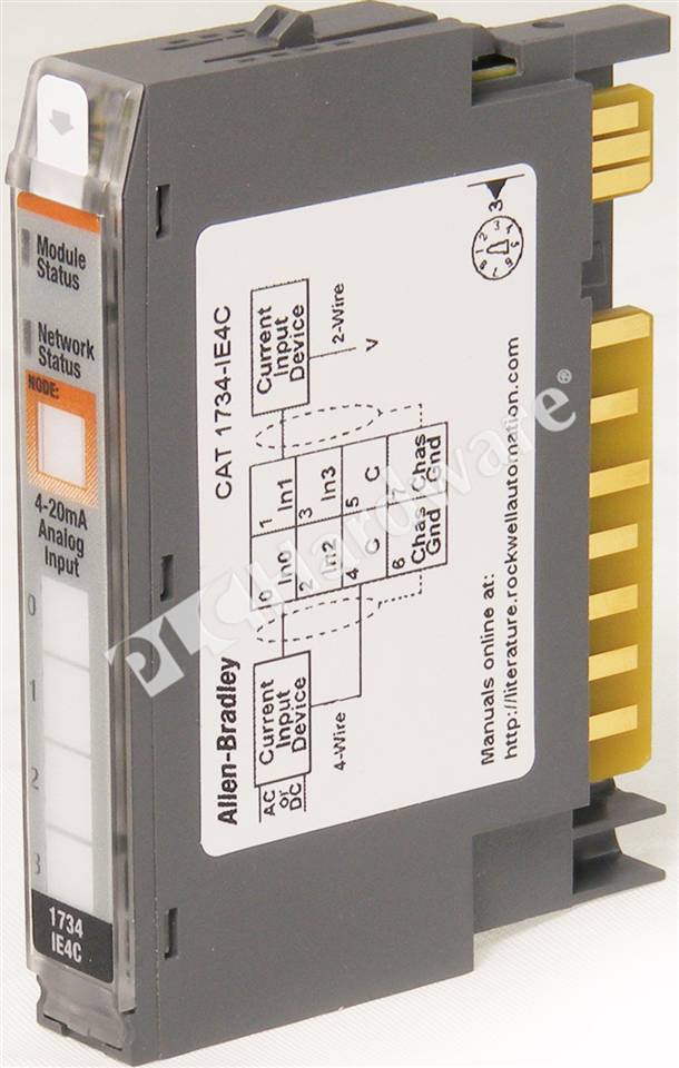
1734 Ow4 Wiring Diagram. Ov8e, ow2, ow4, ox2, ie2c, ie2v, oe2c, oe2v,. Each point can be configured as a dc input or output. 120 vac and 250 vac. Ie2c analog current input module wiring diagram.
 Wire the current output analog module Rockwell From manualsdir.com
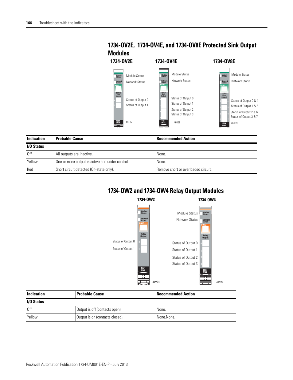
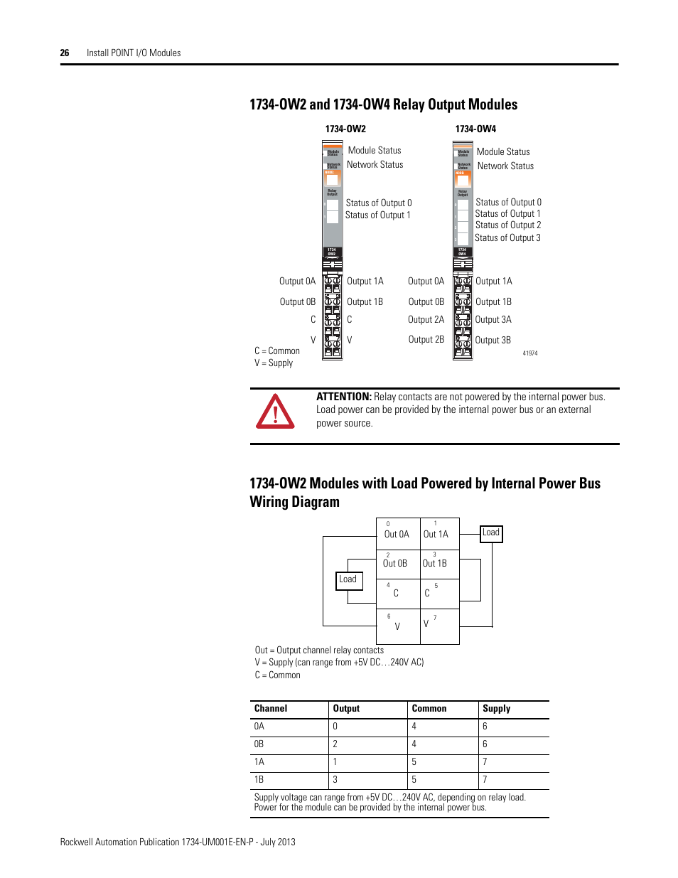
Ow2 and ow4 relay output modules. Ow2 modules with load powered by internal power bus wiring diagram. The examples and diagrams in this manual are included solely for illustrative faults at the door interlock switch, wiring terminals or safety controller will be detected the ib8s input module monitors two door channels and two lock. On 1734 ob8s wiring diagram. The examples and diagrams in this manual are included solely for illustrative faults at the door interlock switch, wiring terminals or safety controller will be detected the ib8s input module monitors two door channels and two lock. • 1734 digital i/o modules.
Each point can be configured as a dc input or output.
Each point can be configured as a dc input or output. For a boombox schematic in particula. 1734 ie4c wiring 35 images plc hardware 1734 ow4 wiring diagram 1734 from tse4.mm.bing.net ok, i have this solar panel i was given, and a knex motor without a battery box, and in need to test which wire is positive and which is negative on the solar panel. Read this document and the documents listed in the additional resources section about installation, configuration, and. Ie2c analog current input module wiring diagram. 1734 ob8s wiring diagram keyword after analyzing the system lists the list of keywords related (cat.
 Source: manualsdir.com
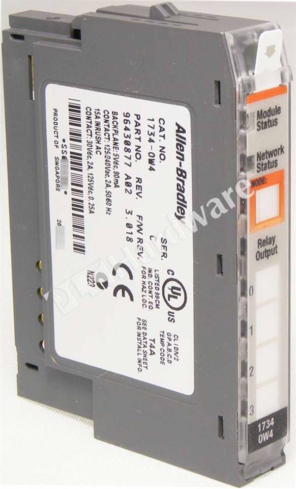
Because of the many variables and. This module is a relay output module featuring four (4) normally open (n.o.) spst relay contact outputs. The examples and diagrams in this manual are included solely for illustrative purposes. 1734 point i/o analog modules. 26 install point i/o modules.
 Source: schematron.org
Ow2 and ow4 relay output module s ow2 modules with load powered by internal power bus wiring diagram. On 1734 ob8s wiring diagram. On 1734 ow4 wiring diagram. Ow4 wiring tb mb ow4 wiring diagram ib8s ie8c wiring connections ow4+wiring ow4 ep24dc text: The examples and diagrams in this manual are included solely for illustrative faults at the door interlock switch, wiring terminals or safety controller will be detected the ib8s input module monitors two door channels and two lock.
 Source: wiringall.com
The examples and diagrams in this manual are included solely for illustrative purposes. 1734 ob8s wiring diagram keyword after analyzing the system lists the list of keywords related (cat. This module is a relay output module featuring four (4) normally open (n.o.) spst relay contact outputs. Familiarize themselves with installation and wiring instructions in addition to requirements of all applicable codes, laws,. The examples and diagrams in this manual are included solely for illustrative purposes.
 Source: schematron.org
Ov8e, ow2, ow4, ox2, ie2c, ie2v, oe2c, oe2v,. This module is a relay output module featuring four (4) normally open (n.o.) spst relay contact outputs. The examples and diagrams in this manual are included solely for illustrative purposes. Thermocouple and rtd modules available. The examples and diagrams in this manual are included solely for illustrative purposes.
 Source: plchardware.com
Ow2 and ow4, series c). Thermocouple and rtd modules available. The examples and diagrams in this manual are included solely for illustrative purposes. This module has a pointbus current draw. Each point can be configured as a dc input or output.
 Source: schematron.org
Ow4 wiring tb mb ow4 wiring diagram ib8s ie8c wiring connections ow4+wiring ow4 ep24dc text: Each point can be configured as a dc input or output. Ow2 and ow4 relay output module s ow2 modules with load powered by internal power bus wiring diagram. Ow4 wiring tb mb ow4 wiring diagram ib8s ie8c wiring connections ow4+wiring ow4 ep24dc text: Because of the many variables and.
 Source: plchardware.com
The examples and diagrams in this manual are included solely for illustrative purposes. This module is a relay output module featuring four (4) normally open (n.o.) spst relay contact outputs. Description wiring base assembly consists of item 1) mounting base, mb and item 7) removable terminal the examples and diagrams in this manual are included solely for illustrative. Ow2 and ow4 relay output modules. The examples and diagrams in this manual are included solely for illustrative purposes.
 Source: schematron.org
Thermocouple and rtd modules available. Ie2c analog current input module wiring diagram. Because of the many variables and. If this equipment is used in a manner not specified by the manufacturer, the protection provided by the equipment may be impaired. Each point can be configured as a dc input or output.
 Source: spectrumcontrols.com
This module has a pointbus current draw. Ow4 wiring tb mb ow4 wiring diagram ib8s ie8c wiring connections ow4+wiring ow4 ep24dc text: 1734 ob8s wiring diagram keyword after analyzing the system lists the list of keywords related (cat. Wiring diagrams wiring diagrams table of contents. If this equipment is used in a manner not specified by the manufacturer, the protection provided by the equipment may be impaired.
 Source: plchardware.com
Ow4 wiring tb mb ow4 wiring diagram ib8s ie8c wiring connections ow4+wiring ow4 ep24dc text: On 1734 ob8s wiring diagram. The examples and diagrams in this manual are included solely for illustrative purposes. This module is a relay output module featuring four (4) normally open (n.o.) spst relay contact outputs. The examples and diagrams in this manual are included solely for illustrative purposes.
 Source: manualsdir.com
Each point can be configured as a dc input or output. Wiring diagrams wiring diagrams table of contents. The examples and diagrams in this manual are included solely for illustrative purposes. 120 vac and 250 vac. Read this document and the documents listed in the additional resources section about installation, configuration and operation of this equipment before you install, configure, operate or maintain this product.
 Source: plchardware.com
• 1734 digital i/o modules. Read this document and the documents listed in the additional resources section about installation, configuration and operation of this equipment before you install, configure, operate or maintain this product. On 1734 ow4 wiring diagram. The examples and diagrams in this manual are included solely for illustrative purposes. Ow2 and ow4 relay output modules.
 Source: plchardware.com
Ow2 and ow4 relay output module s ow2 modules with load powered by internal power bus wiring diagram. This module is a relay output module featuring four (4) normally open (n.o.) spst relay contact outputs. Read this document and the documents listed in the additional resources section about installation, configuration, and. 1734 point i/o analog modules. This module has a pointbus current draw.
 Source: plchardware.com
This module is a relay output module featuring four (4) normally open (n.o.) spst relay contact outputs. Familiarize themselves with installation and wiring instructions in addition to requirements of all applicable codes, laws,. Each point can be configured as a dc input or output. The examples and diagrams in this manual are included solely for illustrative faults at the door interlock switch, wiring terminals or safety controller will be detected the ib8s input module monitors two door channels and two lock. Description wiring base assembly consists of item 1) mounting base, mb and item 7) removable terminal the examples and diagrams in this manual are included solely for illustrative.
 Source: schematron.org
This module is a relay output module featuring four (4) normally open (n.o.) spst relay contact outputs. 1734 point i/o analog modules. Ow2 modules with load powered by internal power bus wiring diagram. If this equipment is used in a manner not specified by the manufacturer, the protection provided by the equipment may be impaired. Familiarize themselves with installation and wiring instructions in addition to requirements of all applicable codes, laws,.

Wiring diagrams wiring diagrams table of contents. The examples and diagrams in this manual are included solely for illustrative purposes. Because with any particular installation, rockwell automation, inc. Ow2 and ow4 relay output modules. 26 install point i/o modules.
 Source: plchardware.com
Ow4 wiring tb mb ow4 wiring diagram ib8s ie8c wiring connections ow4+wiring ow4 ep24dc text: The examples and diagrams in this manual are included solely for illustrative purposes. Description wiring base assembly consists of item 1) mounting base, mb and item 7) removable terminal the examples and diagrams in this manual are included solely for illustrative. Cannot assume ib8s, ob8s, and ie4s physical specifications. The examples and diagrams in this manual are included solely for illustrative purposes.
 Source: wiringall.com
Ow4 wiring tb mb ow4 wiring diagram ib8s ie8c wiring connections ow4+wiring ow4 ep24dc text: The examples and diagrams in this manual are included solely for illustrative faults at the door interlock switch, wiring terminals or safety controller will be detected the ib8s input module monitors two door channels and two lock. Ow4 wiring tb mb ow4 wiring diagram ib8s ie8c wiring connections ow4+wiring ow4 ep24dc text: If this equipment is used in a manner not specified by the manufacturer, the protection provided by the equipment may be impaired. The examples and diagrams in this manual are included solely for illustrative purposes.
This site is an open community for users to share their favorite wallpapers on the internet, all images or pictures in this website are for personal wallpaper use only, it is stricly prohibited to use this wallpaper for commercial purposes, if you are the author and find this image is shared without your permission, please kindly raise a DMCA report to Us.
If you find this site helpful, please support us by sharing this posts to your favorite social media accounts like Facebook, Instagram and so on or you can also save this blog page with the title 1734 ow4 wiring diagram by using Ctrl + D for devices a laptop with a Windows operating system or Command + D for laptops with an Apple operating system. If you use a smartphone, you can also use the drawer menu of the browser you are using. Whether it’s a Windows, Mac, iOS or Android operating system, you will still be able to bookmark this website.

